18 S&C Instruction Sheet 761-545
Installation
If a key interlock is used (standard minor
modification suffix “-S6” or “-S6L”), proceed
to Step 25. Otherwise, proceed to Step 27 on
page 19.
Installing the Key Interlock
STEP 25. The interlock group includes a Superior Type
B4003-1 Mk II single- or multiple-key interlock
(or equivalent), with zero bolt projection and
¾-inch (19 mm) bolt travel, locking disc, and
interlock bracket. If “provision only” is
specied, the interlock is not included.
Attach the key interlock to the interlock
bracket so the interlock bolt, when extended,
engages a slot in the locking disc on the
operating handle. See Figure 25.
STEP 26. Block one of the two slots in the locking disc
with the blocking screw provided. (The slot to
be blocked depends on whether a locked-open
or locked-closed arrangement is required.) See
Figure 26.
NOTICE
Key interlocks are intended for proper
sequencing of switch operations; they are not
intended to provide security. The operating
handle assembly includes a locking bar for
padlocking the switch in either the Open or
Closed position.
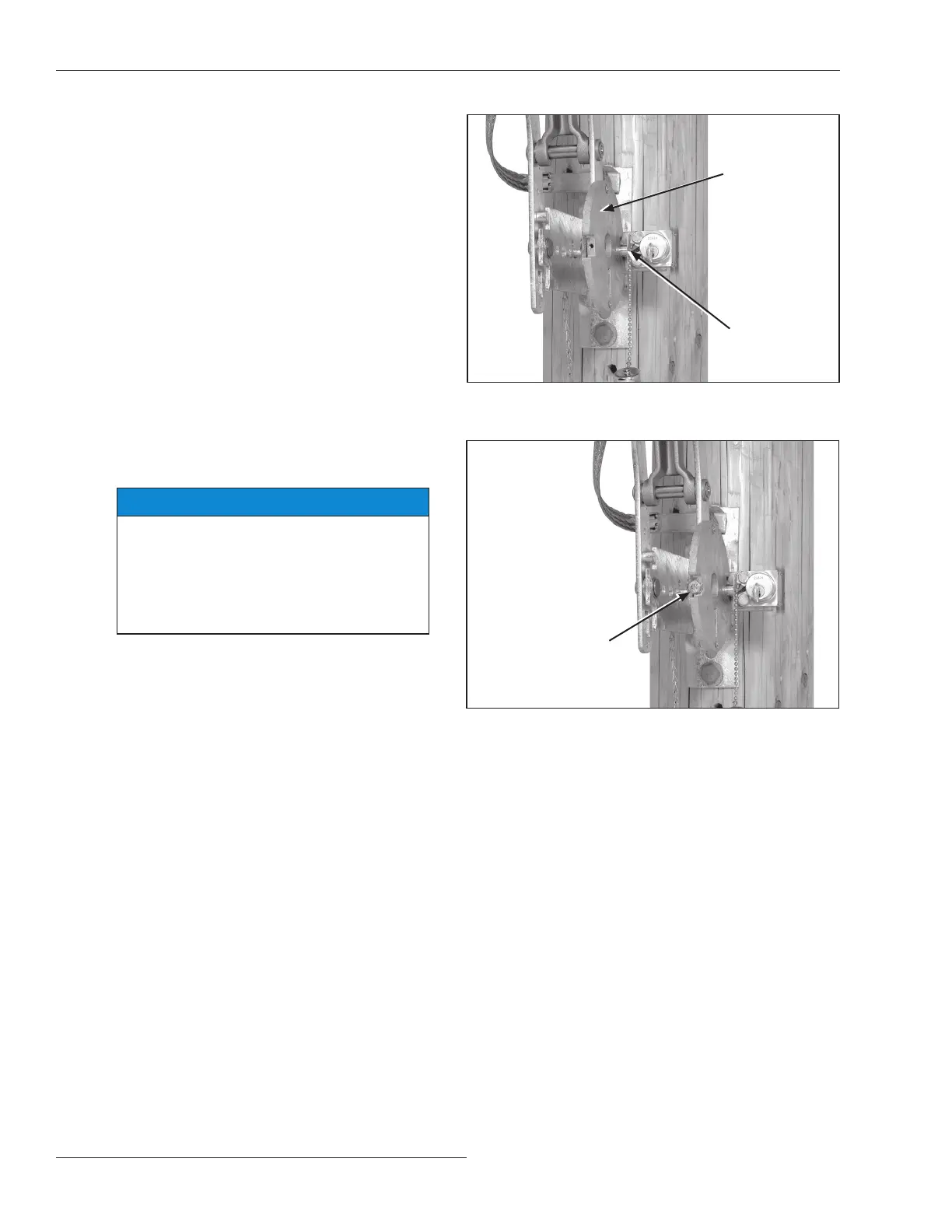
Figure 25. Attaching the key interlock to the interlock
bracket.
Interlock bolt
Blocking screw
Figure 26. The blocking screw in the interlock disc.
Locking disc
 Loading...


