11 656-500
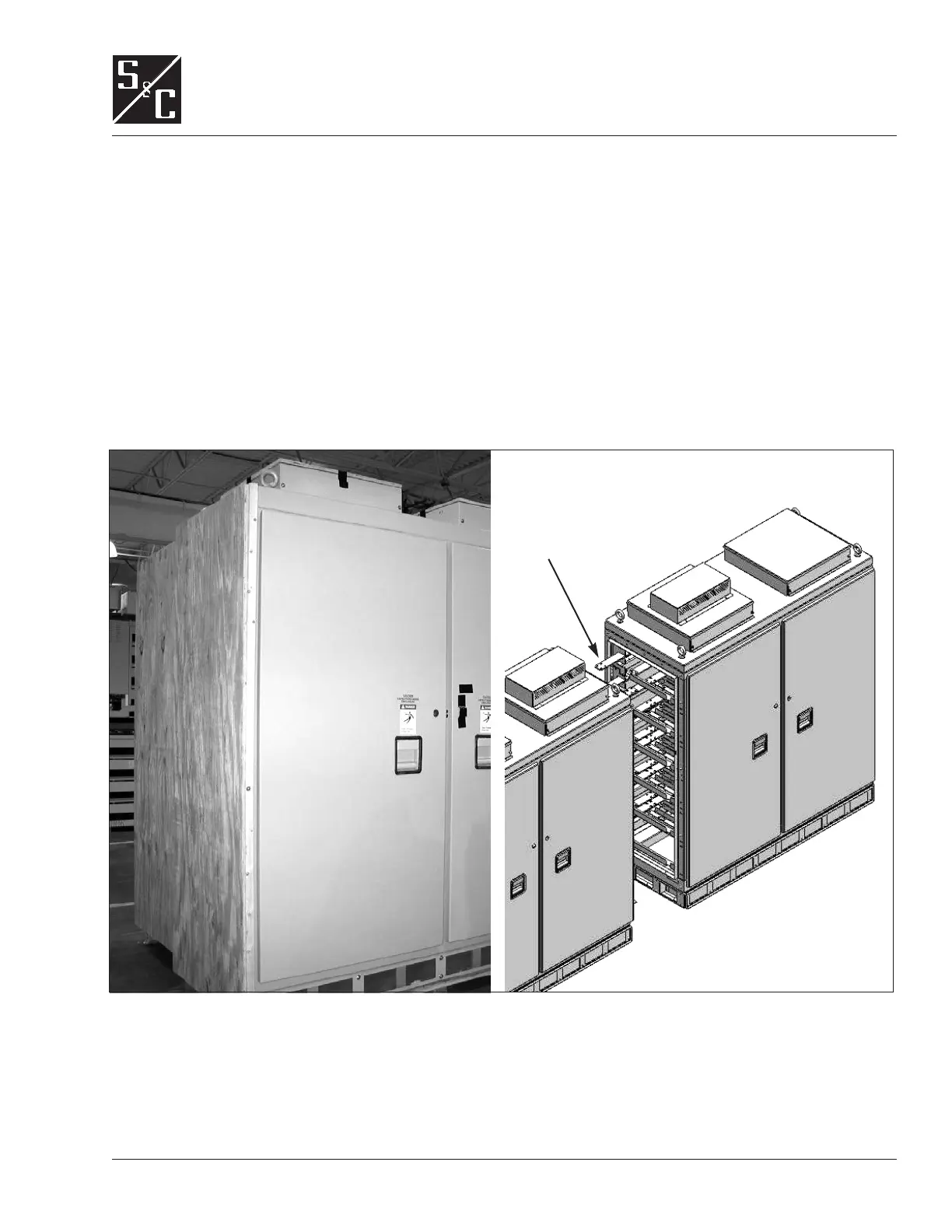
Figure 5. Individual section with wood panel at end. Sections are joined as shown.
INSTALLATION
Assembly If the sections have shipped unassembled, assemble them as follows:
1. Remove the wood panels attached to the ends of the sections. Con-
nect adjacent sections using supplied hardware (eighteen ³⁄₈-16
1¹⁄₂ hex-head bolts, square flat washers, lock washers, and nuts). See
Figure 5. Tighten each bolt to 240 inch-pounds. For outdoor installa-
tions, use supplied gasket material between sections.
2. Install the rear bus splices. See Figure 5 and Figure 6. Thoroughly
abraid the Aluminum buses and splices to remove any dirt or oxida-
tion prior to making the connections. Coat the contact surfaces to
¹⁄₂ inch beyond the joint with a uniform layer of Penetrox® A com-
pound. Attach the splice plates using four ¹⁄₂ hex-head bolts, Belle-
ville washers, and nuts supplied. Tighten each bolt to 480 inch-
pounds.
Rear bus splices
 Loading...
