656-500 16
CABLE CONNECTIONS
Output Connections 1. Open the door of the control section to access the output connec-
tions. See Figures 12 and 13 and the drawings furnished.
Note: The bus construction in the PureWave AVC is typically alu-
minum. Terminal pads on components may be aluminum, copper, or
copper alloy. Hence, bus and terminal connections are typically alu-
minum-to-aluminum or aluminum-to-copper. Such connections
employ Belleville washers. Do not tighten factory-made connections
employing Belleville washers unless they are visibly loose; they have
been correctly torqued to 50 foot-pounds at the factory. Other con-
nections employ flat washers; if they have loosened, they should be
torqued to 35 foot-pounds. Check bus connections and, where nec-
essary, correctly tighten the connecting hardware.
a. For aluminum terminal pads to aluminum connectors: Use alumi-
num or galvanized-steel hardware with two Belleville washers
(not furnished). Torque each aluminum bolt to the manufacturer’s
specifications. Torque each steel bolt to 50 foot-pounds or, in the
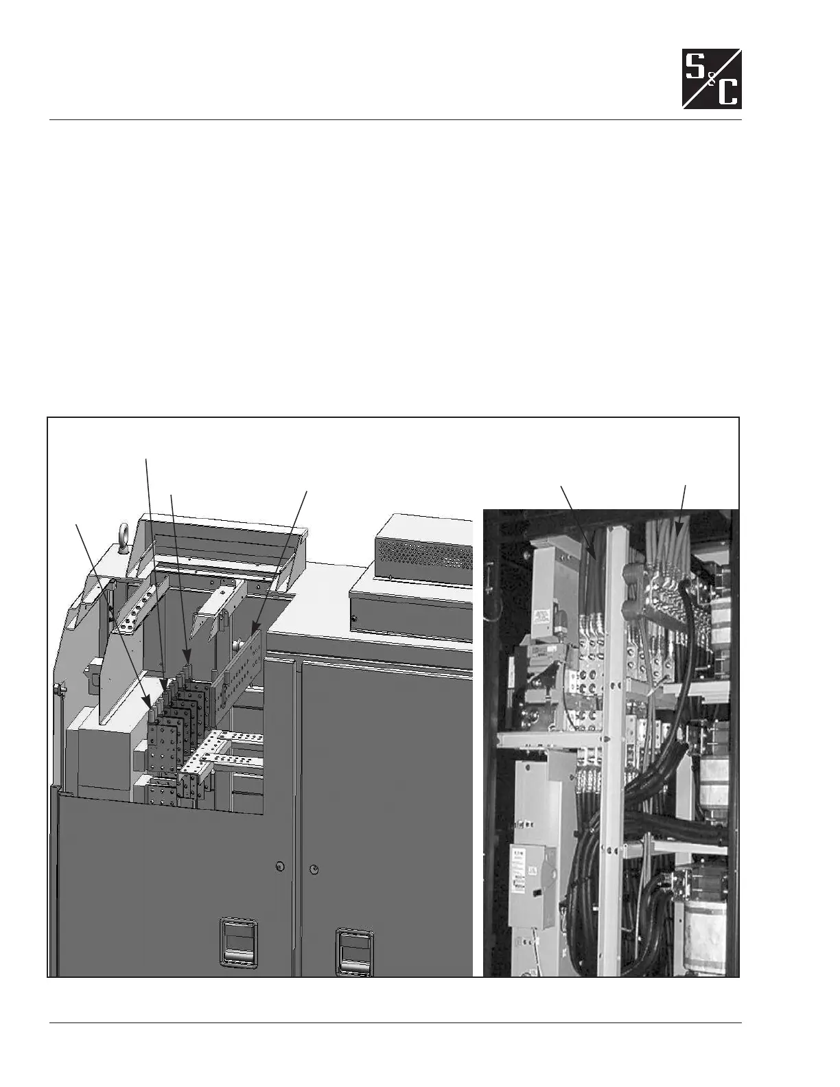
Figure 13. Control section cutaway shown with output connections for overhead raceway, with internal circuit breaker option
(left). Close-up of cable entry area after output connections have been made (right).
Phase C buses
front (2)
Phase B buses
middle (2)
Phase A buses
rear (2)
Neutral bus
Phase
cables
Neutral
cables
 Loading...
