www.SteamPoweredRadio.Com
MAINTENANCE
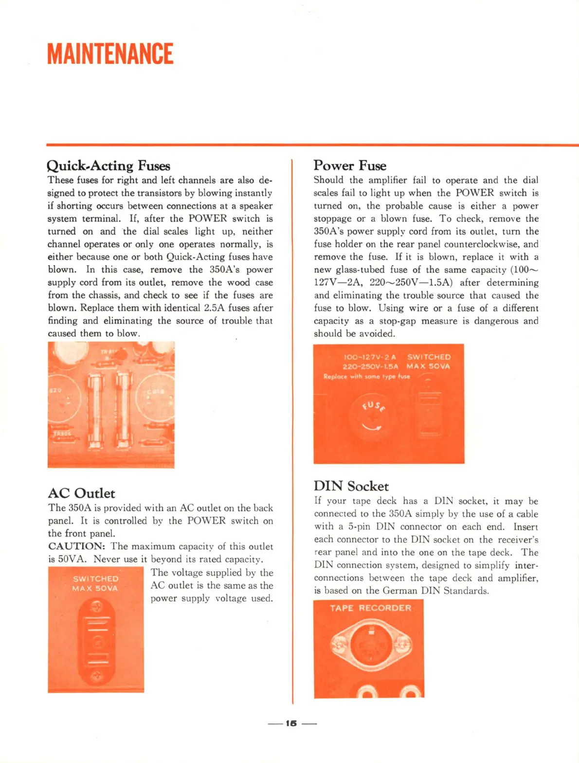
Quick-Acting Fuses
These
fuses for right and left channels are also de-
signed to protect the transistors by blowing instantly
if
shorting occurs between connections at a speaker
system terminal.
If
, after the
POWER
switch
is
turned on and the dial scales
li
ght up, neit
her
channel operates or only one operates normall
y,
is
either
because one or both Quick-Acting fuses have
blown.
In
this case, remove the 3
50A
's power
supply cord from its outlet, remove the wood case
from the chassis, and check to see if the fuses are
blown. Replace them with identical 2.
5A
fuses a
ft
er
finding and eliminating the source of trouble that
caused them to blow.
AC
Outlet
The
350A
is
provided with an
AC
outl
et
on the back
pane
l.
It
is
controlled by the
POWER
switch
on
the front panel.
CAUTION:
T he maximum capacity of this outlet
is
50V A. ever use it beyond its rated capacity.
The voltage supplied by the
AC outlet
is
the same as the
po
wer
supply voltage used.
Power
Fuse
Should the ampli
fi
er
fa
il
to operate and the
di
al
scales
fa
il
to light up when the
POWER
switch
is
turned
on
, the probable cause
is
either a power
stoppage or a blown fuse.
To
check, remove the
350A s power supply cord from its outlet, turn the
fuse holder on the
rear
panel counterclockwise, and
remove the
fu
s
e.
If it
is
blown, replace it with a
new glass-tubed fuse of the same capacity (
100-----
1
27
V
-2
A,
22
0-----
250V- 1.5A) after
de
termining
and eliminating the trouble source that caused the
fu
se to blow. Using wire or a fuse of a different
capacity as a stop-gap measure is dangerous and
should be avoide
d.
DIN
Socket
If
your tape deck has a
Dl
socket, it may be
connected to the 350A simply by the use of a cable
with a 5-pin DIN connector on each end. Insert
each connector to the DI socket
on
the receiver's
r
ear
panel and into the
on
e on the tape deck.
The
DI connection system, designed to simplify inter-
connections between the tape deck and amplifier,
is
based
on
the German DIN
Standard
s.
-
US
-