Do you have a question about the Sansui 6060 and is the answer not in the manual?
Details power output, bandwidth, distortion, and frequency response for audio performance.
Covers FM tuning range, sensitivity, selectivity, and distortion for FM reception.
Details AM tuning range, sensitivity, and selectivity for AM reception.
Includes power requirements, power consumption, and other general specifications.
Procedure for adjusting bias current for amplifier channels.
Detailed steps for FM IF circuit alignment and tracking.
Step-by-step guide for threading the dial cord.
Steps for attaching the dial pointer to the tuning mechanism.
Location and parts list for the power supply circuit board.
Diagrams and parts list for components on the top side of the unit.
Diagrams and parts list for components on the bottom side of the unit.
Schematic diagram for the Sansui 6060 model.
Schematic diagram for the Sansui 5050 model.
Block diagram of the power amplifier and protector circuits.
| Tuning range | FM, MW |
|---|---|
| Power output | 40 watts per channel into 8Ω (stereo) |
| Frequency response | 20Hz to 20kHz |
| Total harmonic distortion | 0.3% |
| Damping factor | 30 |
| Input sensitivity | 2.5mV (MM), 150mV (line) |
| Output | 150mV (line) |
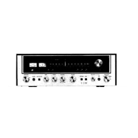
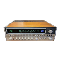
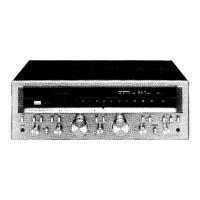
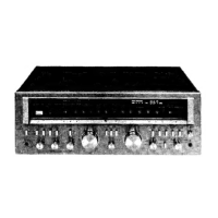
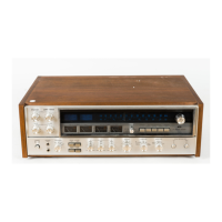
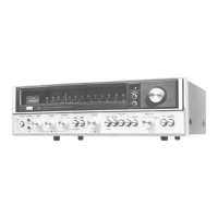
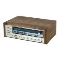
| Type | Receiver |
| Channel separation | 50dB (line) |
| Speaker load impedance | 4Ω to 16Ω |
| Speaker Impedance | 8Ω |