Do you have a question about the Sansui 9090 and is the answer not in the manual?
Detailed specifications for the audio performance, including power output, impedance, distortion, and sensitivity.
Technical specifications for the FM tuner, covering tuning range, sensitivity, selectivity, and distortion.
Technical specifications for the AM tuner, including tuning range and sensitivity.
Covers power requirements, consumption, dimensions, and weight of the receiver unit.
Step-by-step instructions for adjusting the driver circuit board, including bias current and DC offset.
Procedures for fine-tuning and aligning the FM tuner section for optimal performance.
Steps for aligning the AM Intermediate Frequency (IF) stages and tracking for accurate reception.
Instructions for aligning the Multiplex (MPX) section for stereo separation and decoding.
Functional block diagram illustrating the signal flow within the tuner section of the receiver.
Functional block diagram showing the signal path through the audio amplification and control stages.
Identifies common audio section issues, defective circuits, and potential causes for diagnosis.
Lists common tuner section problems, their related circuits, and likely causes for repair.
Location diagram and parts list for the F-2546 Power Supply Circuit Board.
Location diagram and parts list for the F-2547 Protector Circuit Board.
Location diagram and parts list for the F-2543 Tone Control Circuit Board.
Location diagram and parts list for the F-2436 Driver Circuit Board.
Location diagram and parts list for the F-2545 Filter & Muting Circuit Board.
Location diagram and parts list for the F-2541 Equalizer Circuit Board.
Location diagram and parts list for the F-2431 Power Supply Circuit Board.
Location diagram and parts list for the F-2544 Tone Control Circuit Board.
Location diagram and parts list for the F-2542 Accessory Switch Circuit Board.
Location diagram and parts list for the F-2549 FM/AM Tuner Circuit Board.
Location diagram and parts list for the F-2550 Multi-Path Circuit Board.
Location diagram and parts list for the F-1470 Lamp Circuit Board.
Location diagram and parts list for the F-2597 Connector Circuit Board.
Location diagram and parts list for the F-2548 Protector Connector Circuit Board.
Location diagram and parts list for the F-1519 FM Pack unit.
Illustrations and diagrams of semiconductors and connector types used in the unit.
Diagram and list identifying external components and parts visible on the top side of the unit.
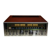
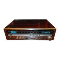
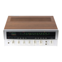
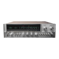
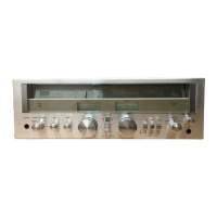
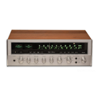
Diagram and list identifying external components and parts visible on the front panel of the unit.
| Power Output | 110 watts per channel into 8Ω (stereo) |
|---|---|
| Total Harmonic Distortion | 0.1% |
| Damping Factor | 30 |
| Input Sensitivity | 2.5mV (MM), 150mV (line) |
| Tuning Range | FM, MW |
| Speaker Load Impedance | 4Ω to 16Ω |
| Channel Separation | 50 dB (1 kHz) |
| Output | 150mV (line) |