7
3.2 LOCATION
3.2.1. The unit should be vertically wall mounted using the screws and plugs provided.
Position the bottom two screws as shown in Figure 1 with heads 3mm from
the wall. Hang the heater and secure with the top screw. Alternatively it can
be oor mounted on it’s base. The water connections must always be to the
top of the unit.
3.2.2 Enough space should be left at the top above the unit for pipe connections and
access to the Temperature/Pressure Relief Valve (if tted). Refer to Figure 1
and the Dimensions Table to determine a suitable position for the heater.
3.2.3 NOTE: Ensure that the wall can support the full weight of the unit (see
TECHNICAL SPECIFICATIONS) and that there are no hidden services,
(electricity, gas, or water) below the surface of the wall.
3.2.4 DO NOT install where the unit may freeze.
3.3 TERMINAL COVER REMOVAL
3.3.1 To remove the terminal cover use a large at bladed screwdriver to relieve
the snaps located towards the front, at either side, of the cover. Gripping the
cover at the front, pull upwards.
3.3.2 To re t the cover, locate the hinge at the back. Slide the snaps into place.
Apply pressure to the front of the cover pushing back and down until it snaps
securely in place.
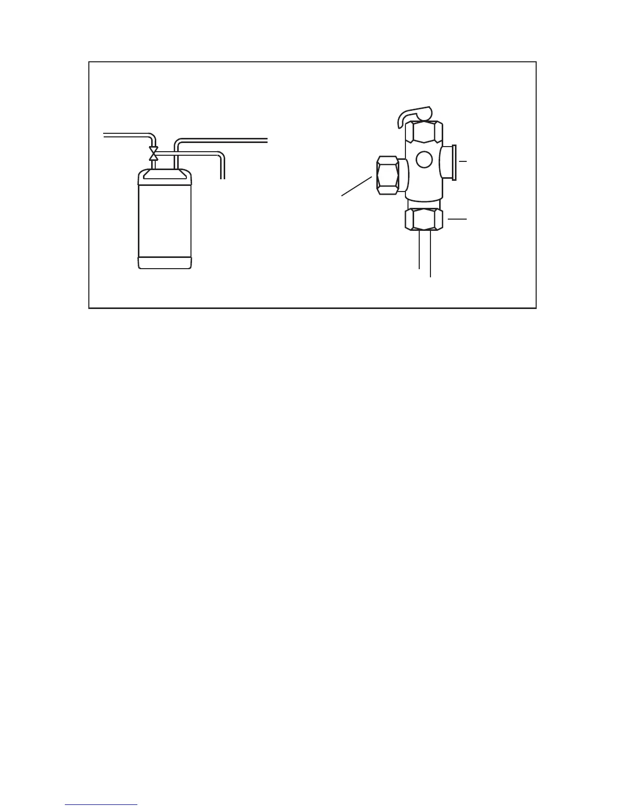
HOT
T&P VALVE
COLD
TO D RA I N
( WA STE)
FIGURE 05: TEMPERATURE AND PRESSURE RELIEF VALVE.
TO D RAI N
( WA STE)
CONNECTION TO
OU TLET PI PE OF
AQUAHEAT WATER
HEA TER.
HOT WATER
OU TLET PI PEWORK
CONNECTION
D ETA I L OF TEM PERATURE
A ND PRESSURE RELI EF VA LVE
PROBE
NOTE: THE FITTING OF ALKO6 (94970013) DOES NOT ALTER THE REQUIREMENTS OF POINTS 1.1 TO 1.4
 Loading...