Do you have a question about the Sanyo Denki PY Series and is the answer not in the manual?
Details the manual's structure, purpose, and how to interpret its content.
Explains the symbols and text formats used throughout the manual.
Provides critical DANGER, WARNING, and CAUTION notices for safe operation and installation.
Information on accessing support resources via the company's website.
Contact details for the technical support center and its operating hours.
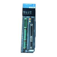
Overview of available PY family servo and stepper drives.
Details on the range of PY family servo and stepper motors.
Information on valid system configurations assembled from motors and amplifiers.
Recommendations for using Sanyo Denki motor power and feedback cables.
Information on optional external regeneration resistors.
Introduces the chapter's content on installing the amplifier and motor.
Steps for unpacking and inspecting the amplifier and motor for damage.
Guidance on general requirements, mounting, and environmental considerations for amplifier installation.
Instructions for motor environmental requirements, mounting, and load connection.
A checklist to ensure all installation steps and conditions are met.
Introduces the chapter's content on wiring the amplifier and motor.
Simplified diagram showing system connections for a PY0 drive.
Simplified diagram showing system connections for a PY2 drive.
Essential safety and best practice guidelines for wiring the system.
Table of recommended wire sizes for various connections.
Details power supply capacity requirements for different system configurations.
Explanation of high-frequency leakage current and its potential effects.
Detailed wiring diagrams for PY2 and PY0 drives with P3/P5 and P2/P6 motors.
Pin assignments and explanations for CNA, CND, and CNB connectors.
Detailed pin assignments and descriptions for the CN1 control connector.
Pin assignments for connecting the motor encoder via the CN2 connector.
Final checklist to verify correct wiring and connections.
Introduces the chapter's content on amplifier operation and timing diagrams.
Information on amplifier status indicators and pre-operation checks.
Details the 7-segment display, power LED, and charge LED for status indication.
Timing diagram and circuit details for the proper amplifier power-on sequence.
Defines sequences for stopping the amplifier due to bus power loss or internal errors.
Describes the sequence for disabling the amplifier, with or without brake delay.
Timing diagram for the procedure to reset alarms and resume normal operation.
Defines the sequence of operation for over-travel conditions.
Guidance on determining if an external resistor is needed based on generated energy.
Table and criteria for selecting the appropriate external regeneration resistor.
Instructions and diagrams for connecting external regeneration resistors.
Diagrams showing dimensions and mounting considerations for regeneration resistors.
Checklist for verifying connections related to external regeneration resistors.
Introduces the chapter containing system, amplifier, and motor specifications.
Formulas and definitions for calculating motor acceleration and deceleration times.
Explanation of internal dynamic brake characteristics and operating frequency.
Details on motor direction of rotation and holding brake specifications.
Introduces setting parameters, viewing history, tuning, and monitoring via Remote Operator/Software.
Guide to configuring and testing the amplifier using the Remote Operator.
Instructions for installing and using the PY Setup Software for configuration.
Procedures for rotating the motor forward and backward using Remote Operator or PY Software.
Explanation of auto-tuning and manual tuning for optimizing amplifier performance.
How to use the Remote Operator or PY Setup Software to monitor amplifier status.
Procedure to view the history of the last eight faults and current alarms.
Steps for common configuration changes like command mode and motor selection.
Introduces the chapter listing all amplifier parameters with descriptions and values.
Overview of how amplifier parameters control and configure functions.
Pictorial reference of parameters associated with position control tuning.
Pictorial reference of parameters associated with velocity control tuning.
Diagram illustrating internal and external current limit parameters.
A table listing all amplifier parameters sorted by Remote Operator mode and page.
Detailed explanations of each amplifier parameter, including their ranges and limits.
Introduces the chapter on maintenance and troubleshooting for installation.
Guidelines for routine maintenance, including cleaning and cable inspection.
Guide to identifying and resolving alarm codes indicated by the amplifier.
Troubleshooting steps for 'OC' alarm related to power element issues.
Troubleshooting steps for 'OL' alarm related to motor overload conditions.
Troubleshooting steps for 'AOH' alarm related to amplifier overheating.
Troubleshooting steps for 'OV' alarm related to overvoltage conditions.
Troubleshooting steps for 'OS' alarm related to exceeding maximum speed.
Troubleshooting steps for 'PE' alarm related to control power supply issues.
Troubleshooting steps for 'DE' alarm related to encoder or sensor faults.
Troubleshooting for 'MPE' alarm related to bus power supply failure.
Troubleshooting for 'FP' alarm related to missing phase in bus power.
Troubleshooting steps for 'SE' alarm related to velocity control errors.
Troubleshooting for 'OVF' alarm indicating position deviation overflow.
Troubleshooting for 'EXOH' alarm related to external resistor overheating.
Troubleshooting steps for 'DSPE' alarm related to DSP malfunctions.
Troubleshooting for 'RGOH' alarm related to internal resistor overheating.
Troubleshooting for 'RGOL' alarm related to regeneration capacity or resistors.
Troubleshooting steps for 'MEME' alarm related to memory errors.
Troubleshooting steps for 'CPUE' alarm related to CPU failures.
| Series | PY Series |
|---|---|
| Type | Servo Drives |
| Position Control | Yes |
| Speed Control | Yes |
| Torque Control | Yes |
| Control Method | PWM Control |
| Communication | RS-485 |
| Protection Functions | Overcurrent, Overvoltage, Overheat, Short Circuit |
| Operating Temperature | 0°C to 55°C |
| Humidity | 20% to 85% RH (non-condensing) |