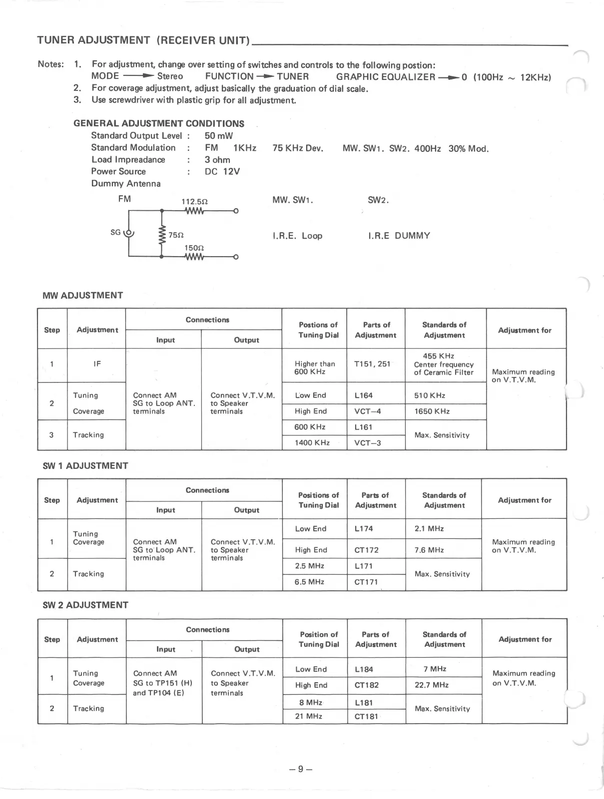
TUNER ADJUSTMENT (RECEIVER UNIT) ____________________ _
Notes: 1. For adjustment, change over setting of switches and controls to the following postion:
MODE ., Stereo FUNCTION -TUNER GRAPHIC EQUALIZER -o (100Hz ~ 12KHz) ,,--
2. For coverage adjustment, adjust basically the graduation of dial scale.
3. Use screwdriver with plastic grip for all adjustment.
GENERAL ADJUSTMENT CONDITIONS
Standard Output Level
Standard Modulation
Load lmpreadance
Power Source
Dummy Antenna
50mW
FM 1KHz
3 ohm
DC 12V
75 KHz Dev.
MW. SW1.
I.R.E. Loop
MW ADJUSTMENT
Connections
Postions of
Step
Adjustment
Tuning Dial
Input
Output
1
IF Higher than
600 KHz
Tuning Connect AM
Connect V.T.V.M.
Low End
2
SG to Loop ANT. to Speaker
Coverage
terminals terminals
High End
600 KHz
3
Tracking
1400 KHz
SW 1 ADJUSTMENT
Connections
Positions of
Step
Adjustment
Tuning Dial
Input Output
Tuning
Low End
1 Coverage Connect AM Connect V.T.V.M.
SG to Loop ANT. to Speaker High End
terminals terminals
2.5 MHz
2
Tracking
6.5 MHz
SW 2 ADJUSTMENT
Connections
Position of
Step
Adjustment
Tuning Dial
Input Output
Tuning
Connect AM Connect V.T.V.M.
Low End
1
Coverage SG to TP151 (H)
to Speaker
High End
andTP104 (E)
terminals
8 MHz
2
Tracking
21 MHz
-9-
MW. SW1. SW2. 400Hz 30% Mod.
SW2.
1.R.E DUMMY
Parts of Standards of
Adjustment Adjustment
455 KHz
T151, 251
Center frequency
of Ceramic Filter
L164 510 KHz
VCT-4 1650 KHz
L161
Max. Sensitivity
VCT-3
Parts of Standards of
Adjustment Adjustment
L174 2.1 MHz
CT172 7.6 MHz
L171
Max. Sensitivity
CT171
Parts of Standards of
Adjustment Adjustment
L184
7 MHz
CT182
22.7 MHz
L181
Max. Sensitivity
CT181
Adjustment for
Maximum reading
on V.T.V.M.
'
Adjustment for
Maximum reading
on V.T.V.M.
Adjustment for
Maximum reading
on V.T.V.M.
I
-../