~
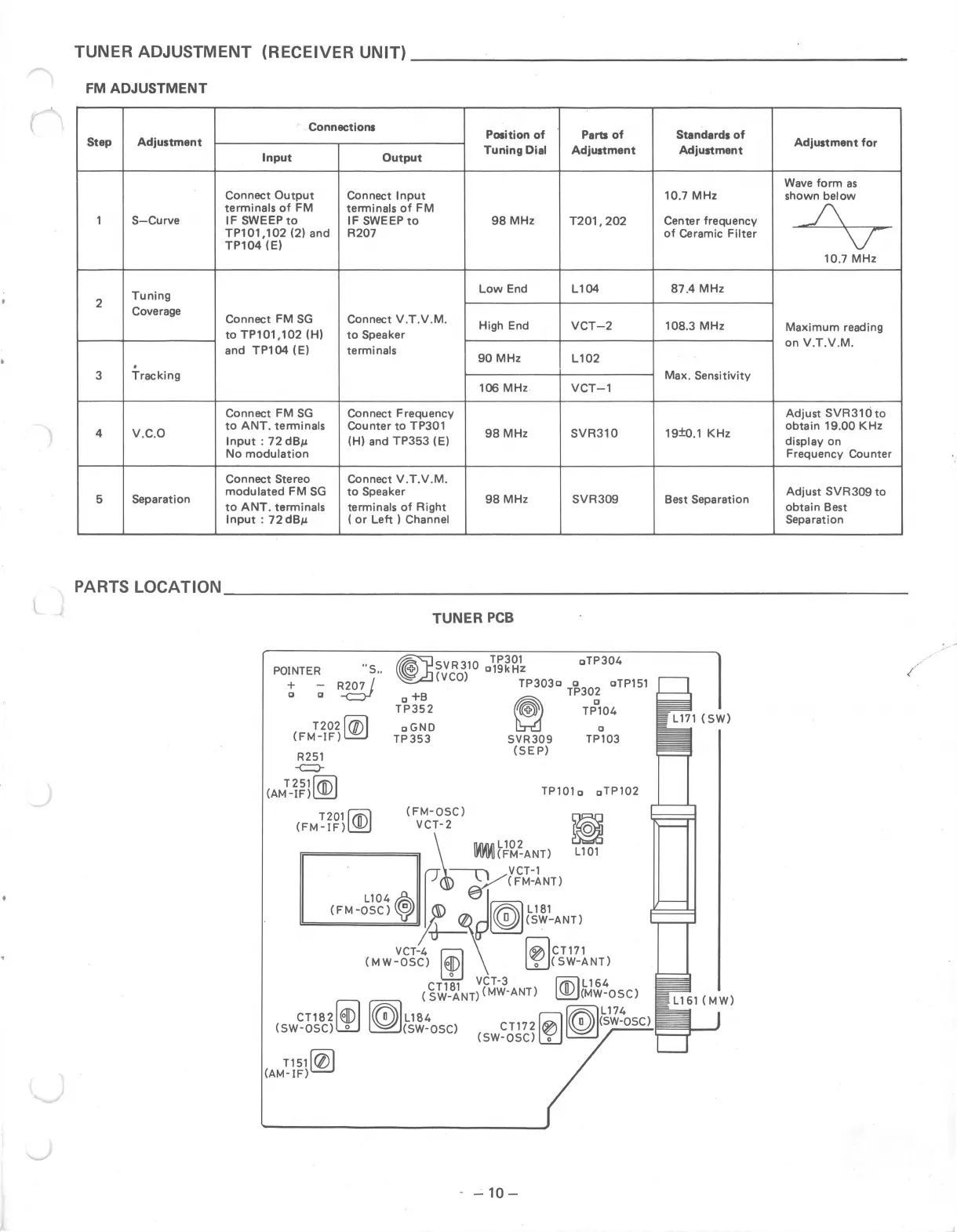
TUNER ADJUSTMENT (RECEIVER UNIT) ____________________ _
FM ADJUSTMENT
Connections
Position of Parts of Standards of
Step Adjustment
Tuning Dial Adjustment Adjustment
Adjustment for
Input Output
Wave form as
Connect Output
Connect Input 10.7 MHz shown below
terminals of FM
terminals of FM
J\
1 S-Curve IF SWEEP to IF SWEEP to 98 MHz
T201, 202 Center frequency
TP101, 102 (2) and R207
of Ceramic Filter
\T
TP104 (El
10.7MHz
Tuning
Low End
L104
87.4 MHz
2
Coverage
Connect FM SG Connect V.T.V.M.
High End
VCT-2 108.3 MHz
Maximum reading
to TP101,102 (HI to Speaker
on V.T.V.M.
and TP104 ( El
terminals
90 MHz
L102
.
3
Tracking Max. Sensitivity
106 MHz VCT-1
Connect FM SG
Connect Frequency
Adjust SVR31cito
4
v.c.o
to ANT. terminals
Counter to TP301
98 MHz SVR310 19±o.1 KHz
obtain 19.00 KHz
Input : 72 dBµ (HI and TP353 (El
display on
No modulation Frequency Counter
Connect Stereo Connect V.T.V.M.
5
Separation
modulated FM SG to Speaker
98 MHz SVR309 Best Separation
Adjust SVR309 to
to ANT. terminals
terminals of Right obtain Best
Input : 72 dBµ ( or Left I Channel
Separation
PARTS LOCATION ____________________________ _
POINTER ··s ..
!
~
R}g!)
T202~
(FM-IF)~
R251
--c:::)-
T 251 l(ll}
(AM-IF)~
T 2 01 1/ii\11([)1
(FM-IF)~
CT182~
csw-oscilJ:J
T151fqj)
(AM-IF)~
TUNER PCB
~SVR310
"~~~~k
c,TP304
~(VCO) TP303o o oTP151
+B
~
TP30~
TP352
~
TP104
oGND D
TP353 SVR309 TP103
(SEP)
TP101 o oTP102
- -10-