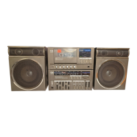
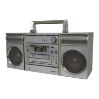
DECK/AMP ADJUSTMENT (DECK UNIT) ____________________ _
Notes:
1.
For adjustment, change over settings of switches, and controls to the following posistions:
REC. MUTE
~
OFF DOLBY NR - OFF
METAL/NORMAL ., NORMAL
2. Conditions of adjustment
Power Supply voltage : DC 12V
Input point in recording :
LINE IN terminals.
Reference of recording level Set the attenuator so that 1 V at the input point becomes O dB.
ITEM OF ADJUSTMENT
TAPE USED
ADJUSTING METHOD
Reproduce DOLBY NR tape,
and adjust SVR 401
Reproducing output (P.B. GAIN) DOLBY NR tape
(SVR501) so that the
reproducing output appearing
(MTT-150, for instance) over the LINE OUT
L-ch (R-ch) becomes 560 mV.
Record
1
kHz and 10 kHz
at -30dB level, and
then
reproduce recording.
Recording/ playback Noiseless recording tape
frequency response (AC 223, for instance)
Adjust SVR 601 (SVR 602) so that reproducing output
(BIAS) existing over the LINE OUT L-ch (R-ch)
becomes O dB
for 1 kHz or O ± 3 dB for 10 kHz.
Record 1 kHz at -10 dB
level. Adjust SVR 402
Recording/ reproducing out put
Noiseless recording tape
(SVR 502) so that the reproducing output which appears
(AC 223, for instance) at the LINE
IN L-ch (R-ch) when reproducing thus
recorded becomes 350 mV.
Noiseless recoding tape
Record 1 kHz at +10 dB level.
Adjust SVR 403 so that
ALC
(AC212, for instance)
the reproducing output of LINE OUT (L-ch) and LINE
OUT (R-ch) became O ± 1dB level between two channels.
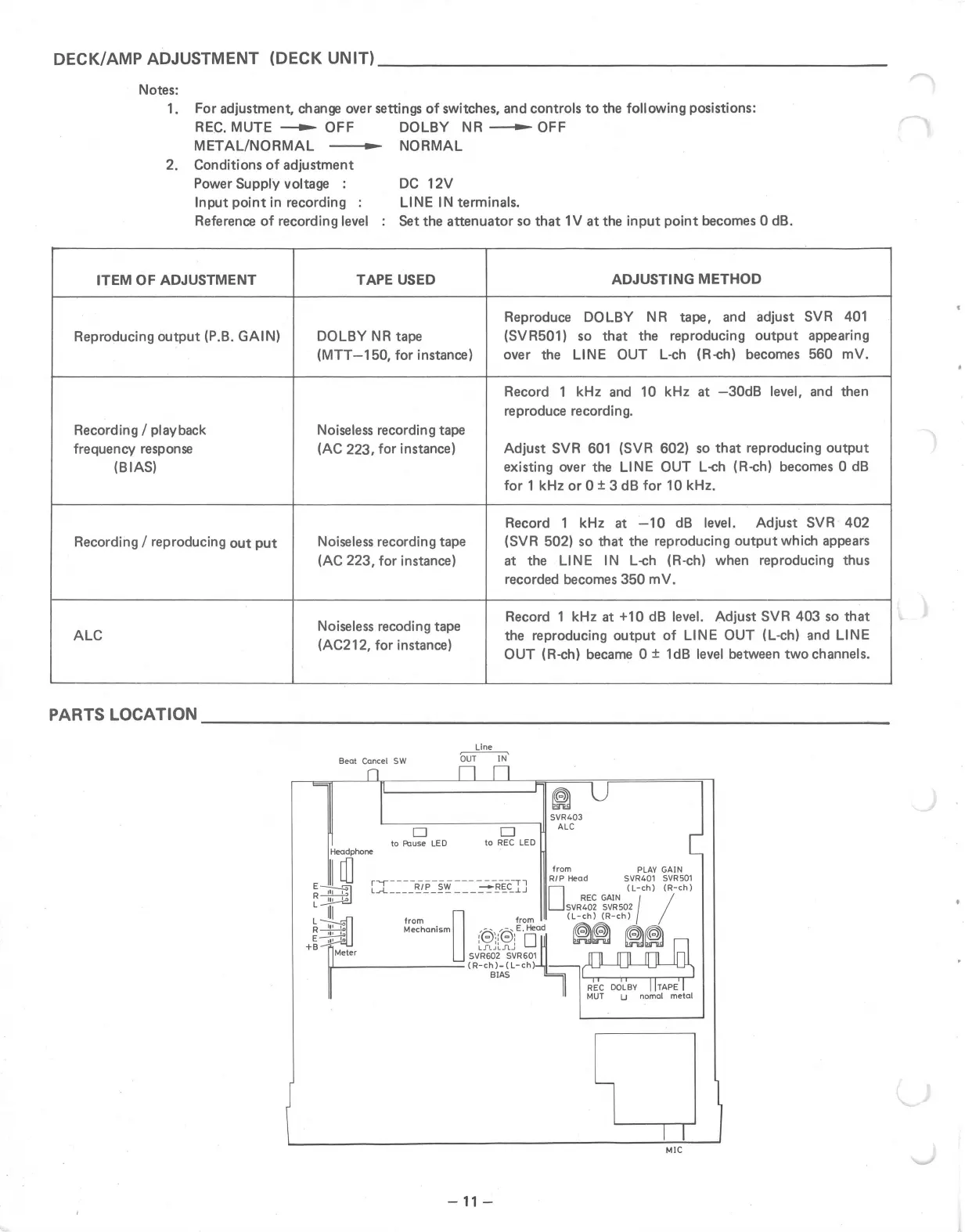
PARTS LOCATION ____________________________ _
Line
OUTIN
D
D
to REC LED
-11 -
~
SVR403
ALC
MIC
r""\,
,,-