EasyManua.ls Logo

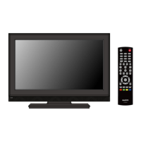
Sanyo LCD-42XF7 User Manual

Sanyo LCD-42XF7
50 pages
To Next Page IconTo Next Page
Page #1 background imageLoading...
Page #1 background image
SERVICE MANUAL
LCD Television
N7YW
FILE NO.
Model No. LCD-42XF7
(Argentina)
Give complete “SERVICE REF. NO.” for parts order
or servicing. It is shown on the rating label at the
cabinet back of the unit.
This T.V. receiver will not work properly in for-
eign countries where the television transmis-
sion system and power source differ from the
design specifications. Refer to the specification
table.
Service Ref. No. LCD-42XF7-00
Product Code:113022517
Original Version
Chassis Series: UE6-L
Contents
Safety Notice . . . . . . . . . . . . . . . . . . . . . . . . . . . . . . . . . 2
Specifications . . . . . . . . . . . . . . . . . . . . . . . . . . . . . . . . . 3
Chassis Block Diagrams . . . . . . . . . . . . . . . . . . . . . . . . 4
IC Block Diagrams . . . . . . . . . . . . . . . . . . . . . . . . . . . . . 6
On-screen Service Menu System . . . . . . . . . . . . . . . . 14
Service Adjustments. . . . . . . . . . . . . . . . . . . . . . . . . . . 20
Mechanical Disassembly . . . . . . . . . . . . . . . . . . . . . . 21
Cabinet Parts List. . . . . . . . . . . . . . . . . . . . . . . . . . . . . 25
Chassis Electrical Parts List. . . . . . . . . . . . . . . . . . . . . 27
Printed Wiring Board . . . . . . . . . . . . . . . . . . . . . . . . . . 45
Aclaración :
Los modelos 42LC822F marca Noblex , PLF4210 marca Philco y LT42R50 marca
JVC utilizan los mismos circuitos , la diferencia es la gabinetería.
Question and Answer IconNeed help?

Do you have a question about the Sanyo LCD-42XF7 and is the answer not in the manual?

Sanyo LCD-42XF7 Specifications

General IconGeneral
Screen Size42 inches
Display TechnologyLCD
Aspect Ratio16:9
HDMI Ports3
Brightness500 cd/m²
Response Time6 ms
Power Consumption220W
Resolution1920 x 1080
Contrast Ratio10000:1
Viewing Angle178°
Input PortsComponent, Composite, VGA
Sound Output20W

Summary

Safety Notice

Safety Precautions

General safety guidelines for operating and servicing the TV.

Product Safety Notice

Warnings regarding component replacement for safety.

Specifications

Chassis Block Diagrams

Main Signal Processing Circuit

Block diagram of the main signal processing flow within the TV.

Power Supply IC

Block diagram illustrating the power supply IC and its connections.

Schematic Diagram

Detailed schematic of the main board, showing component interconnections.

IC Block Diagrams

IC601 QL6599DTR Block Diagram

Functional block diagram of the QL6599DTR integrated circuit.

IC602 QL6562ADTR Block Diagram

Functional block diagram of the QL6562ADTR integrated circuit.

IC603 QFAN7602M Block Diagram

Functional block diagram of the QFAN7602M integrated circuit.

IC702 QRT9711CGB Block Diagram

Functional block diagram of the QRT9711CGB integrated circuit.

IC750 QPS331TQFP64M Block Diagram

Pinout and functional block diagram of the QPS331TQFP64M IC.

IC1501 TC4052 Block Diagram

Pinout and functional block diagram of the TC4052 analog multiplexer.

IC1801 QPCA9536DGKRP Block Diagram

Pinout and functional block diagram for the QPCA9536DGKRP I/O expander.

IC8000 QXXAAJQ1148 Block Diagram

Functional block diagram of the QXXAAJQ1148 IC.

IC8001 MST6M16 Block Diagram

Pinout and functional block diagram of the MST6M16 main processor.

IC8002 QXXAVC951 Block Diagram

Functional block diagram of the QXXAVC951 IC.

IC8005 QXXAVC961M Block Diagram

Pinout and functional block diagram of the QXXAVC961M IC.

On-screen Service Menu System

General

Overview of the on-screen service menu system for adjustments.

How to Enter the Service Menu

Step-by-step instructions to access the service menu.

Side Controls

Visual guide to the remote control buttons used for service menu navigation.

How to Select Service Item and Adjust Data

Guide on navigating and modifying service parameters within the menu.

Service Adjustment Data Table

Table listing service items, initial data, and associated ICs.

Service Adjustments

CAUTION!

Important warnings regarding service adjustments to prevent performance loss.

Setting the Initial Data

Procedure for setting initial data, especially after component replacement.

White and Black Balance Adjustment

Steps for adjusting white and black balance for picture quality.

Mechanical Disassembly

Disassembly Diagram

Exploded view illustrating the TV's main components for disassembly.

STAND Removal

Instructions for safely removing the TV stand.

LID BACK Removal

Procedure for removing the rear cover (lid back).

ASSY, PWB, POWER Board, ASSY, PWB, MAIN Board and TERMINAL BASE Removal

Steps to remove major internal boards and terminal base.

CABINET BACK Removal

Instructions for removing the main cabinet back panel.

SPEAKER Removal

Procedure for detaching the TV's speakers.

DEC IND RC Board Removal

Steps for removing the remote control receiver board.

Cabinet Parts List

Chassis Electrical Parts List

Printed Wiring Board

Main Board (Part Side) Layout

Top-side layout diagram of the main printed wiring board.

Main Board (Solder Side) Layout

Bottom-side layout diagram of the main printed wiring board.

Power Board (Part Side) Layout

Top-side layout diagram of the power supply board.

Power Board (Solder Side) Layout

Bottom-side layout diagram of the power supply board.
Related product manuals