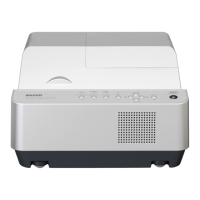
PDG-DXT10L
- 11-
2-7-3 Timing signal processing
The scaler work with an external clock signal of 48MHz & 50MHz.
2-7-4. Audio signal processing
• The audio output is generated from the speakers via the amplifier (U900) provided with a
volume control.
• The volume control is conducted by the DC output from the D/A converter (U900).
2-7-5 System control
The scaler (U400) controls all of this system.
2-7-6 Power circuit
6-1. Main power supply
• In the state of standby, the power is supplied 5V to the scaler, scaler peripheral ICs,
and FLASHROM.
• After the power is ON, the power at 2.5V, 3.3V, 5.7Vand 13V is fed to the analog circuit,
fan, formatter board, etc.
6-2. Lamp power supply
• The lamp is lit with POWER ON.
• Unlighting detection is performed.
2-7-7 Safety design
• Fan circuit detection
• Lamp cover detection
• Lamp house temperature detection
• Thermal protector for the lamp power supply
• Lamp replacing time
 Loading...