G
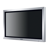
1. The terminal section is screwed in from the outside, so remove the screws
as shown in the illustration.
䚷䐟 6 Hexagonal-Head nuts. Serial terminal, DVI IN terminal, PC IN terminal
(SPECIAL SCREW)
䚷䐠 Qty. 3...AV IN terminal (SCR TPG BRZ 3X8)
䚷䐡 Qty. 2...HDMI terminal (SCR PAN 3X6)
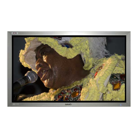
5. Replacement method for main board and jack board
2. Remove 1 screw on the jack board that screws in the
earth terminal which comes off from the left side of the
main board. (SCR PAN+SW+W 3X8)
3. Remove the 7 screws that screw the shield casing onto
the main board. (SCR PAN+SW+W 3X8)
4. Remove the coupler that is connected to the main board,
and then carefully remove the main board.
䚷 Couplers on the main board:
K16C, KSPR, KSPL, KLVP, K16B, K16A, K8F, K72E, K72D
5. Replace the main board with the repair board.
䐟 䐟
䐟 䐟
䐟 䐟
䐠
䐠
䐡
䐡
䐠
Shield casing
K8F
Earth terminal
Main board
Power board
Jack board
LVDS earth wire
䕔Precautions when removing and installing
䞉
The lead wire is affixed to the shield casing on the
main board with aluminum foil tape. Re-use the shield
casing with the lead wire affixed as is.
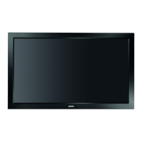
䞉
The gasket is affixed to both sides of the main board.
The gasket is not included on the repair board, so
replace the gasket at the same time as well.
Gasket
(AW-N6EE Qty. 1)
Horizontally, it is positioned roughly in
the center. Vertically, it is affixed along
the depression.
It is positioned 5-10 mm from the edge.
Vertically, it is positioned roughly in
the center.
Gasket
(AW-N4TE Qty. 2)
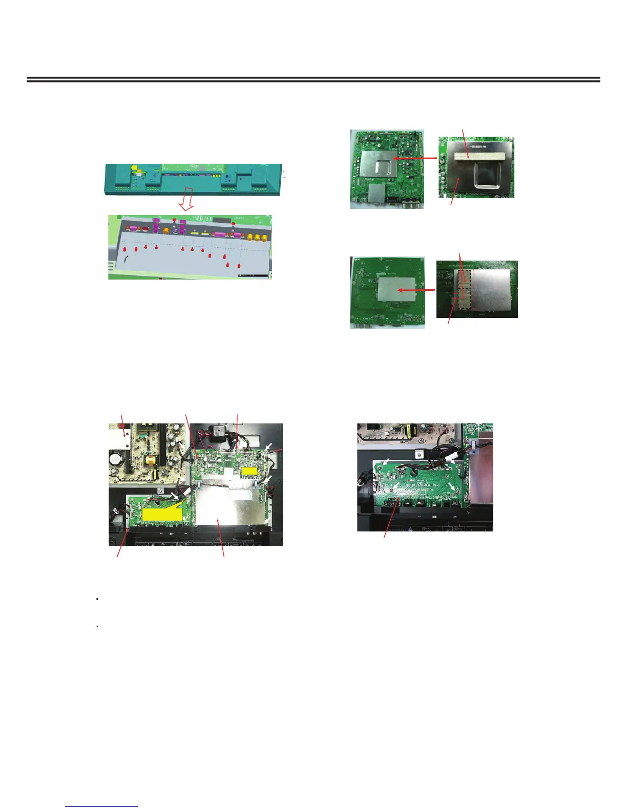
6. Remove the 4 screws that screw in the jack board.
(SCR PAN+SW+W 3X8)
7. Remove the couplers that is connected to the jack board
and carefully remove the jack board.
䚷 Couplers on the jack board: K39H, K39G, K19F, K10E,
K10D
8. Replace the jack board with the repair board.
Jack board
 Loading...