䕔Precautions when removing and installing
䞉
Be careful not to strip the screw's thread, etc., as the
screws that screw into the cabinet back's periphery
impact the outward appearance.
䞉
When re-installing the rear cover, be careful which holes
the wires come out from. (Refer to the wiring connection
diagram)
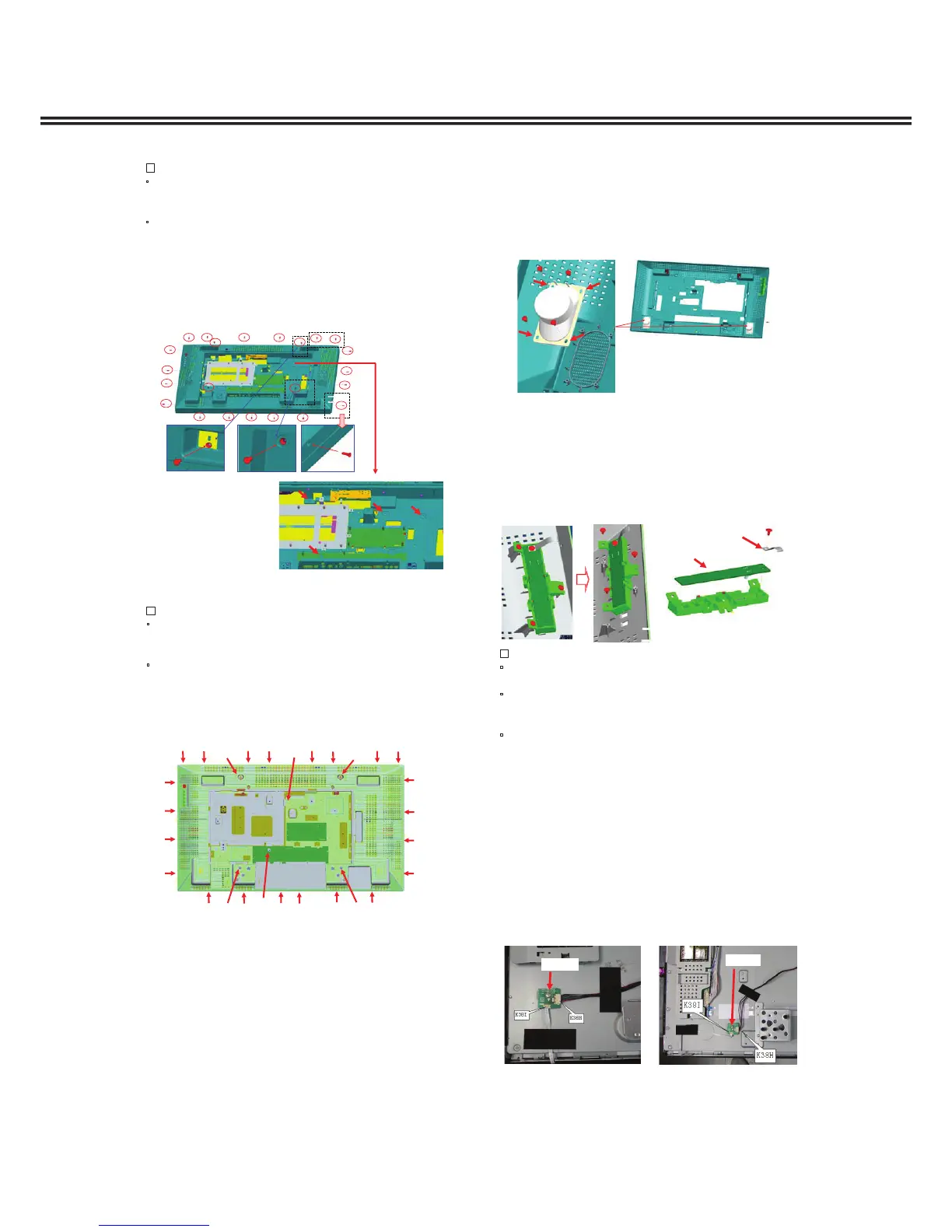
1. Remove the screws (Qty. 23) on the periphery of the
cabinet back. (SCR FLT 4X12)
2. Remove the screws (Qty. 4) on the inside part of the rear
cover. (SCR BIN 4X6)
3. Remove the cabinet back carefull
.
8. Cabinet back removal (42 type)
1. Remove the screws.
䚷(䐟 SCR FLT 4X12 Qty. 26, 䐠 SCR BIN 4X6 Qty. 2)
9. Cabinet back removal (47 type)
2. Remove the cabinet back carefully.
䕔Precautions when removing and installing
䞉
Be careful not to strip the screw's thread, etc., as the
screws that screw into the cabinet back's periphery
impact the outward appearance.
䞉
When re-attaching the cabinet back, be careful which
holes the wires come out from. (Refer to the wiring
connection diagram)
䐟
䐟
䐟
䐟 䐟
䐟
䐠
䐟
䐟
䐟
䐟
䐟
䐟
䐟
䐟
䐟
䐟
䐟
䐟
䐠
䐟
䐟
䐟
䐟
䐟
䐟
䐟
䐟
1. Remove the following board couplers.
Jack board: K39H
Main board: KLVP
Power board: KIV1, KIV2
2. Remove according to the previous section "Cabinet back
removal."
10. When removing the cabinet back
with the board connected
1. Remove the cabinet back.
2. Peel off the tape halfway that affixes the speaker lead on
the inside of the cabinet back, and then remove the
speaker lead. (Refer to the wiring connection diagram)
3. Remove the screws (Qty. 4 on each side) that screw in
the speaker unit and then replace it with the repair
speaker unit. (SCR S-TPG BRZ+FLG 3.0X8.0 V)
䕔Precautions when installing
䞉
For the earth part on the key SW board, do not forget
to install so the key SW board is at a right angle.
䞉
Secure the speaker and key SW board lead wires
down onto the inside of the cabinet back with tape
so they do not pop up.
䞉
When re-attaching the rear cover, be careful which
holes the wires come out from. (Refer to the wiring
connection diagram)
11. Replacement method for speakers
1. Remove the cabinet back.
2. Peel off the tape halfway that affixes the lead wire for the
key SW board on the inside of the cabinet back, and then
remove the lead wire. (Refer to the wiring connection
diagram)
3. Remove the 4 screws and replace the key SW board.
(SCR S-TPG BRZ+FLG 3.0X8.0 V)
12. Key SW board replacement
Key SW board
Earth part
1. Peel off the tape halfway that affixes the FFC cable and
lead wire for the connector board to the rear side of the
LCD panel, and remove them from the rear side of the
panel. (Refer to the wiring connection diagram)
2. Remove the FFC cable (K38I) and the coupler (K38H)
from the connector board.
3. Remove the screw (Qty. 1), and remove the connector
board from the rear side of the LCD panel, and then
re
 Loading...