䕔Precautions when replacing the LCD panel
䞉
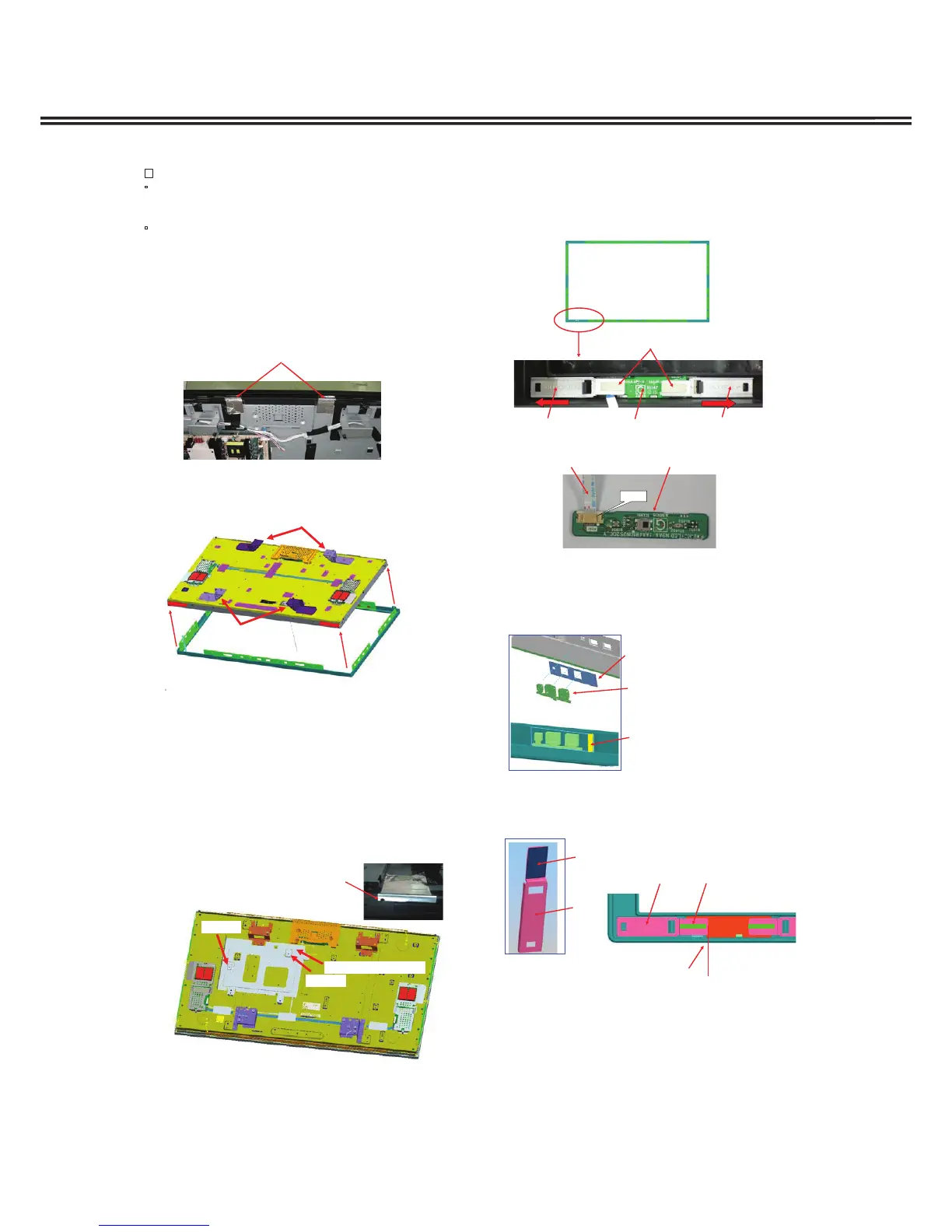
The 2 lead wires for the inverter (Couplers KIV1 and
KIV2), the black-out tape and the spacer sheet, etc., are
supplied already affixed to the LCD panel.
䞉
The tape that is affixed to the FFC cable and the lead wires
on the connector board are supplied as repair parts.
Replace them at the same time as the LCD panel.
1. Follow the procedure mentioned previously, and remove the
connector board, the FFC cable and the lead wire from rear
side of the LCD panel.
2. Peel off the 2 pieces of aluminum foil tape that are affixed to and
cross over the rear side of the LCD panel and the upper part
of the mounting that connects the cabinet front and LCD
panel.
14. LCD panel replacement
3. While widening the mounting that connects the cabinet
front and the LCD panel, remove the cabinet front from
the LCD panel. When lifting up the LCD panel, hold the
mounting component.
Aluminum foil tape
3. Remove the screws (Qty. 8), and then remove the
mounting from the rear side of the LCD panel.
(SCR BIN 4X6)
4. (47V type only) Remove the screws (Qty. 2) and then
remove the Power board holder fittings from the rear side
panel. (SCR BIN 4X4)
䚷*The Power board holder fittings are not available in the
repair parts.
5. Replace the LCD panel with the repair LCD panel.
6. Use 2 pieces of repair aluminum foil tape and cover the
screw hole on the upper part of the mounting so it is
affixed to and crosses over the mounting top and the
rear side of the LCD panel.
47 type
Board holder fitting
Screw
Screw
Mountin
Illustration
for 42 type
1. Slide the 2 fittings on the inside of the cabinet front toward
the outside and remove.
2. Remove the FFC cable from the RC+LED board's coupler
(K19I), and replace the board with the repair board.
15. Replacement method for RC+LED
board
K19I
FFC cable RC+LED board
Fittin
RC+LED board
3. When replacing the cabinet front, remove the shield RC
and the DEC LED (clear plate) on the inside.
The gasket is affixed to the shield RC. When replacing,
also replace the gasket.
Shield RC
DEC LED
Gasket
RC B
4. The spacer sheet and the gasket are affixed to the
fittings that hold down the RC+LED board.
When replacing the fittings, also replace the spacer
sheet and the gasket.
Fitting
Spacer Sheet
Gasket Main
PWB
Screw
hole
Gasket
The fittings on the right and left
should be set to the end and are
positioned so they are vertically
centered.
Fitting
 Loading...