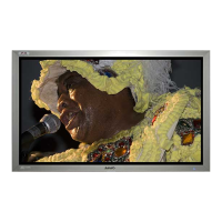
4. (42 type only) Remove the screws shown in the
illustration, and then remove the Power board holder
fitting. (SCR S-TPG BRZ+FLG 3.0X8.0 V)
䕔Precautions when replacing
䞉
The parts that are necessary for replacement (DEC
button, DEC AV, etc.) are not included. They are
supplied as repair parts. Replace them at the same
time as the cabinet back.
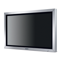
17. Cabinet back replacement
Terminal holder
Power board holder fitting
(Only for 42V type)
Main board holder fitting
1. Remove each board, speaker and fitting from the cabinet
back.
8. Install the repair cabinet back, that is prepared
beforehand, onto the set.
䕔Precautions for replacing
䞉
The terminal holder fitting, the main board holder
fitting, and the Power board holder are available in
the repair parts.
䞉
Use the gasket with the holder fitting that is
affixed as is.
䞉
The type of tape for affixing, in order to set up the
lead wire on the rear side of the cabinet back, is not
included. When replacing the cabinet back, also
replace the type of tape that is used.
Power board
holder fitting
3. Remove the screws shown in the diagram, and then
remove the main board holder fitting.
(42V type: Qty. 1 SCR S-TPG BRZ+FLG 3.0X8.0 V)
(47V type: Qty. 3 SCR S-TPG BRZ+FLG 3.0X8.0 V䠅
42 type
Main board
holder fitting
47 type
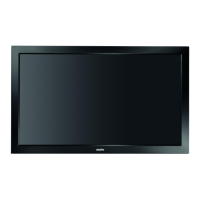
Terminal holder fitting
SLIDE
SLIDE
Main board
holder fitting
2. Remove the screws (Qty. 4) shown in the illustration,
and remove the terminal holder fitting.
(SCR S-TPG BRZ+FLG 3.0X8.0 V)
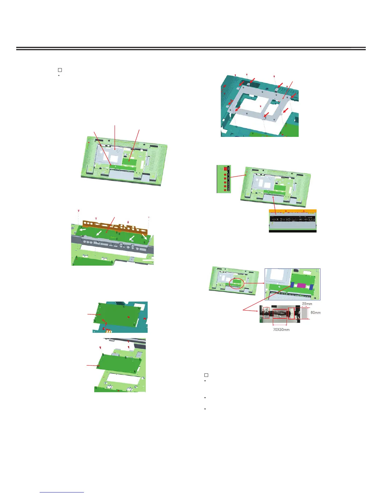
5. Affix the DEC button and DEC AV beforehand to the
repair cabinet back.
DEC Button
DEC AV
6. Install the main board holder fitting and the terminal
holder fitting to the repair cabinet back.
7. Affix 3 pieces of aluminum tape to the metal section of
the main board holder fitting and the terminal holder
fitting so they are connected.
T-ALUMINUM
㻞㻡㼙㼙
㻢㻜㼙㼙
㻣㻜㼄㻡㻜㼙㼙
 Loading...