2
2 - 28
Design of Mini ECO-i SYSTEM
3. Installation Instructions
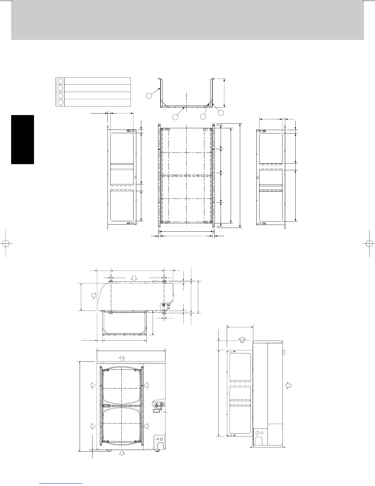
3-6. Dimensions of Air-Discharge Chamber
Reference diagram for air-discharge chamber (field supply)
STK-DRE140A for SPW-CR365/485/605GX(H)56(A/B)
24029.5
29.5
35537317 70
Rectangular
hole
Rectangular
hole
Rectangular
hole
Rectangular
hole
300
2
1
4
3
240
35317537 70
54425 25
569
1090
997
250
250
310250
1 Unit front, air discharge chamber
2 Unit left side, air discharge chamber
3 Unit light side, air discharge chamber
4 Reinforcement brackets, 4 locations
110660170
13 13
340
405
3801015
2020
13
68 544
300
Wind
direction
Wind direction
940
18
1230
Wind
direction
Wind
direction
Wind
direction
Wind
direction
300
108997
Wind direction
Wind direction
Unit: mm
3-7. Dimensions of Outdoor Unit with Air-Discharge Chamber (field supply)
SPW-CR365/485/605GX(H)56(A/B) with STK-DRE140A
06-405 Mini-ECOi_TD2 11/6/06 5:15 PM Page 28

 Loading...