17
Installation of a Pit Frame
− Remove the screws (7), washers and the metal plates of the pit frame
− Place tape over the threads of the pit frame
− Lower the frame into the pit
− Ensure that the contact areas of the pit frame (1), (2), (3) and (4) are completely level
− The pit frame must carry at least half the maximum weighing capacity of the platform on each side
− Adjust the height by placing thin metal plates (7) underneath the pit frame. Back fill with concrete and allow area to
dry.
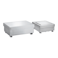
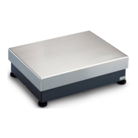
Positioning and Connecting the Weighing Platforms (Your Sartorius Service Technician Will Help You )
− Remove the load plate, the level indicator and leveling feet
− Take the 4 hexagon bolts, M 10x70, from the set of fasteners, YAS 04 IS, attach the locknuts to them and screw
them into the threads for the leveling feet (foot screws). Tighten the bolts.
− Remove the transport locking devices as described on page 7.
− Loosely attach the 4 angular braces to the frame of the weighing platform using the screws (7) and washers from the
set of fasteners.
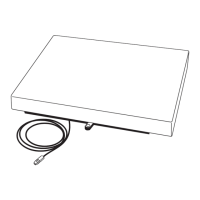
− Push the connecting cable through the tube (6) and lower the weighing platform into the pit frame.
− Loosely attach the angular braces to the pit frame using the screws of the pit frame.
− Center the weighing platform with respect to the pit frame.
− Adjust the height of the weighing platform with the 4 hexagon bolts (9), M 10x70. Fix the screws with the locknuts
and tighten the screws of the angular braces.
− Refit the load plate.
− Use the handles provided in the set of fasteners to remove the load plate.
Pit Construction Diagrams:
 Loading...