PM130 PLUS QuickStart www.satec-global.com
CONNECTION
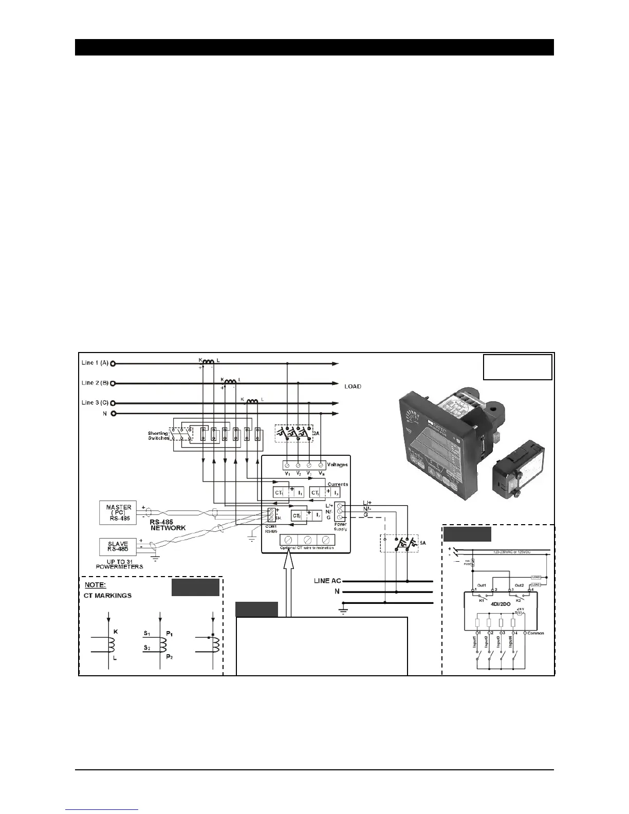
To connect follow these steps (Figure 2 shows a 4W LV installation with conventional CTs):
1. Ensure that all incoming power sources are OFF.
2. Check that you have the appropriate power supply.
3. Connect the Power Supply inputs using 1.5 mm²/14AWG dedicated wires and breaker.
4. Connect to the external CTs by passing the external CTs wires through the meter CT cores.
Observe the arrow that indicates the current direction (Figure 2A). For HACS: connect the
red or white wire to the “-” and orange or black wire to the “+“ terminal.
5. In case of a retrofit application where each external CT ends with two wires (Note 2B):
5.1. Pass one wire through the meter CT core.
5.2. Connect the wire to one of the meter “optional CT wire termination” screws.
5.3. Connect the second wire from the external CT to the termination screw.
6. Connect the measured voltage inputs
7. Connect COM1 – RS-485 communication port
8. To connect the optional module:
8.1. Make sure that the power is turned off
8.2. Remove the module cover
8.3. Attach the module and fasten the screws
8.4. Connect the module I/O or communication (see Figure 2C for DI/O wiring)
9. Turn the power up
10. Make sure the diagnostic led is off
The “optional CT wire termination”
allows connection of the two wires
from the CTs. They have no internal
connection and their use is optional.