PM172 Quick Start Guide
Series PM172 Powermeters
5
Electrical Installation
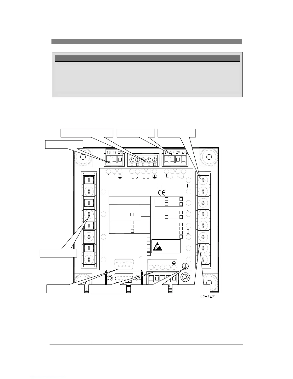
The figure below shows all the connectors and terminals on the rear side of the
PM172.
+RX
16
RS-422/RS-485
POWER SUPPLY
-RX-TX +TX
VN
9 6
1413 15
11
5
V
3
8
Handle Only at
COM.1
1
Workstations
Static-Safe
COM.2
Static-Sensitive
Devices
ATTENTION
17
N/-
L/+
12
10
9
2
1
10-16VDC
18-36VDC
36-72VDC
2V
5
(24)
(48)
(12)
O
S/N
S
N
LOW DC
CT.
I
1A
T
DIGITAL INPUTS
90-264VAC
50/60Hz
85-290VDC
POWER SUPPLY
V
1
2
10W
O
P
ANALOG OUTPUTS
2018 19
12
23
+
21 22
+
262524
3
7
6
2
4
1
-
3
RELAYS
+
1
2928
27
21
ANALOG INPUTS
ANALOG IN/OUT :
+1mA
-
0-20mA
4-20mA
0-1mA
+
+
-
-
--
CALIBRATED AT :
25 Hz
60 Hz
50 Hz
400 Hz
COM.1 :
RS-232/422/485 STANDARD
ETHERNET
MODEM
PROFIBUS
690V
OPT.U
STANDARD
CT.
5A
Figure 6: Connections and Terminals
The diagrams below show typical installations of the PM172.
Digital Inputs
Analo
e Inputs
COM1 Port COM2 Port
Power Supply
IMPORTANT!
Only qualified personnel can perform setup.
All incoming power sources must be turned off during installation. During operation of the
Powermeter, hazardous voltages are present on the input terminals. Failure to observe precautions
can result in serious or even fatal injury, or damage to equipment.
Refer to the installation and operation manual for further information.
 Loading...


