PM172 Quick Start Guide
Series PM172 Powermeters
7
The typical installation diagram above shows a 4-Wire Wye 2½-element
connection using 2 PTs and 3 CTs. The wiring mode is 3LL3 or 3Ln3. The voltages
must be balanced for the configuration to provide accurate power measurements.
There are approximately nine different wiring configurations in the PM17X Series.
Refer to the Installation and Operational Manual for additional configurations.
For electrical installation of the display panel follow the following steps:
1. Connect the remote display using the pinout tables below, either for a
self-powered display or a remote powered display. Refer to the
Installation and Operation Manual for the wiring schematic diagrams.
Pinout for a self-powered remote display
PM172
D15 Female
Pinout
Signal
Remote
Display
D15 Male
Pinout
1 +12V 1
5 RS-485 + (plus) 5
7 RS-485 - (minus) 7
8 GND 8
15 Chassis 15
Pinout for a remote display powered from an external 12V DC,
350 mA power source
PM172
D15 Female
Pinout
Signal
Remote
Display
D15 Male
Pinout
1 N.C. +12V 1
5 RS-485 + (plus) 5
7 RS-485 - (minus) 7
8 N.C. GND 8
15 Chassis 15
2. Connect the DC or AC power.
3. Connect the chassis ground.
4. Connect the required wiring configuration.
5. Connect the I/O connections as required. For I/O ratings, see the
Technical Specifications section in the Installation and Operation Manual.
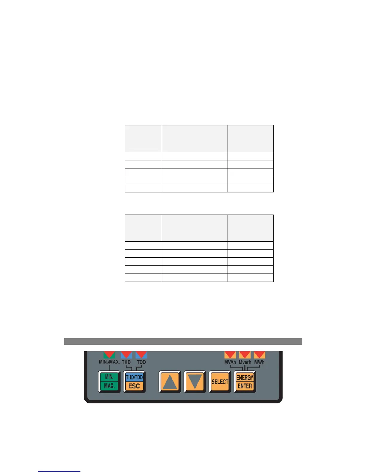
Using the Navigation Buttons
Figure 9: Navigation Buttons
 Loading...


