SATEL ETHM-1 3
Connection to the public network may only be done through a router or xDSL
modem.
The module should be installed indoors, in spaces with normal humidity of air.
1. Set the module address (see SETTING THE ADDRESS).
2. Install the module in the enclosure. If the control panel is to be configured via the Ethernet
(TCP/IP) network using the DLOADX program, the module must be installed in the same
enclosure with the control panel.
3. Connect the module terminals to the control panel terminals as shown in Table 1 (you can
also use another control panel power output to supply the module). To make
a connection, it is recommended that an unshielded straight-through cable be used. When
using the twisted pair type of cable, keep in mind that CKM (clock) and DTM (data)
signals must not be sent through one pair of twisted wires.
ETHM-1 INTEGRA VERSA
+12V +KPD KPD
COM COM COM
DTM DTM DTA
CKM CKM CLK
Table 1.
4. Connect the enclosure tamper switch to the TMP and COM terminals (or connect the
TMP terminal to the COM terminal).
5. Connect the module to the Ethernet network. Use a cable compatible with the
100Base-TX standard (identical to that used when connecting computer to the network).
6. If the control panel is to be configured via the Ethernet (TCP/IP) network using the
DLOADX program, connect the module RS-232 port to the control panel RS-232 port.
Depending on the control panel, the connection must be made with one of the following
cables (these cables are available from SATEL):
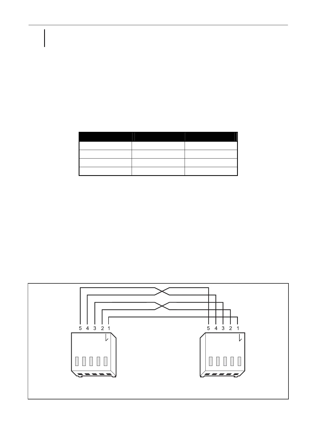
INTEGRA with PIN5 type socket: PIN5/PIN5 (see Fig. 2)
INTEGRA / INTEGRA Plus with RJ type socket: RJ/PIN5 (see Fig. 3)
VERSA: PIN5/RJ-TTL
Fig. 2. Schematic of the cable used to connect the RS-232 ports of ETHM-1 module and
INTEGRA control panel with PIN5 socket.