4 ETHM-1 SATEL
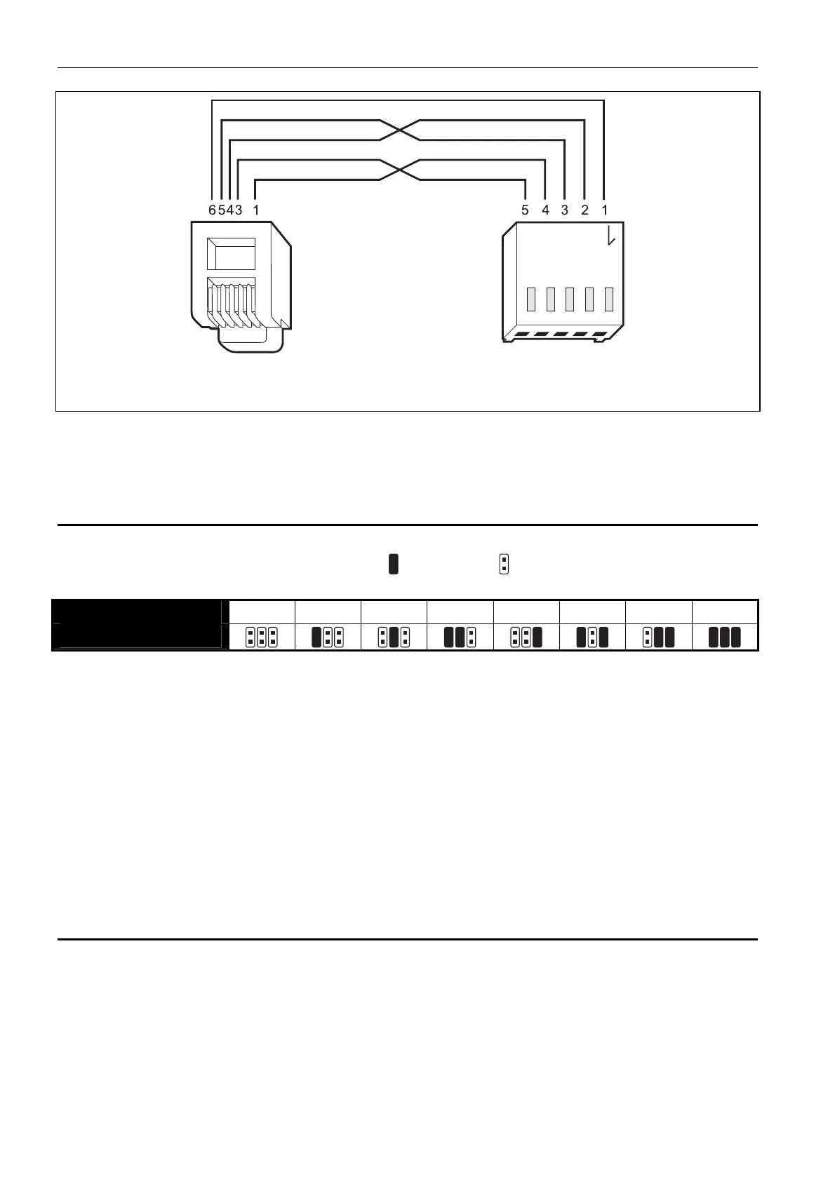
Fig. 3. Schematic of the cable used to connect the RS-232 ports of ETHM-1 module and
INTEGRA / INTEGRA Plus control panel with RJ type socket.
7. Power-up the alarm system.
8. Start the device identification function in the control panel (see the installer manual for the
respective control panel).
4.1 Setting the address
The address is set by means of jumpers placed across the ADR pins. Table 2 shows how to
place the jumpers to set a specific address ( - jumper on; - jumper off).
Address
0 1 2 3 4 5 6 7
Pins status
Table 2.
4.1.1 Interfacing with INTEGRA / INTEGRA Plus control panel
Set the address in the 0 to 3 range (for INTEGRA 24 / INTEGRA 32) or in the 0 to 7 range
(INTEGRA 64 / INTEGRA 128 / INTEGRA 64 Plus / INTEGRA 128 Plus). The address set
must be different from that in the other devices connected to the keypad bus of the control
panel (the control panel does not support devices with the same address).
4.1.2 Interfacing with VERSA control panel
Address 4 must be set in the module. No keypad with the address 4 may be connected to the
control panel.
5 Programming
Programming is done by means of the control panel, using the keypad or the computer
running the DLOADX program.