RFID User Guide 7 PN: 9001147D
CALIBRATION MODE
The Calibration Mode typically appears following the RFID Mode. Use the printer’s Operator or Service Manual for
guidance on the specific menu structure for that printer and how to maneuver to the Service Mode and beyond.
The Configuration Mode menu will only appear on applicable printer’s with the required devices installed.
If using RFID labels that are printer specific, RFID transponder calibration is not necessary because the printer will
automatically place the labels in the optimal programming position. Contact SATO America Technical Support for
inlay + placement specifications as necessary.
Where printer specific RFID labels are not to be used or in cases of new inlay types, RFID calibration may be
required to determine the optimal programming position and transmission/reception power conducive to that
media.
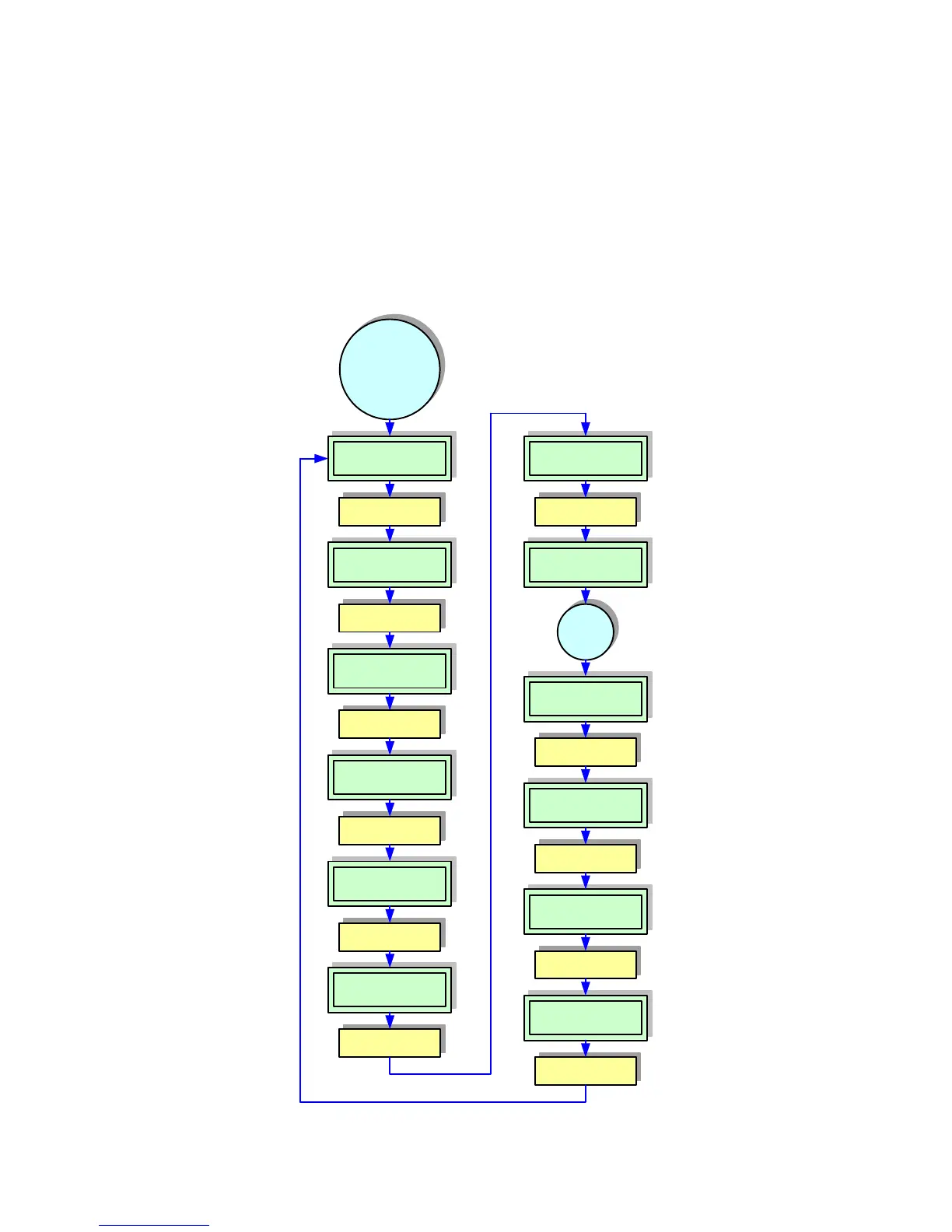
Figure 4, Calibration Mode Flow Chart
Use operator panel to
scroll and advance.
ANTENNA POWER
XXXmW
Label
printed
Use operator panel to
advance.
CALIBRATION MODE
Use operator panel to
scroll and advance.
Use operator panel to
scroll and advance.
Use operator panel to
scroll and advance.
Use operator panel to
advance.
Use operator panel to
scroll and advance.
Use operator panel to
scroll and advance.
Use operator panel to
scroll and advance.
TAG OFFSET
AUTO MANUAL
CALIBRATING. .
P:XXX Ap:XX.XdBM
CAL. START
YES NO
MAX. WRITE COUNT
XXX
CAL. LABEL CNT
1 2 3
LABEL SIZE
XXXMM
PRINT AGAIN
YES NO
RFID TAG OFFSET
+XXXmm
The
Calibration Mode is
entered through the
printer’s menus and
typically follows the
RFID Mode.
Use operator panel to
scroll and advance.
SET LABEL
YES NO
Use operator panel to
scroll and advance.
CAL. OVER
FINISH PRINT