14
201,5
40 mini
33
42
10365
40 mini
3%
Ø B
Ø B
Ø A
Ø A
Ø B
Ø A
Ø A
Ø A
201,5
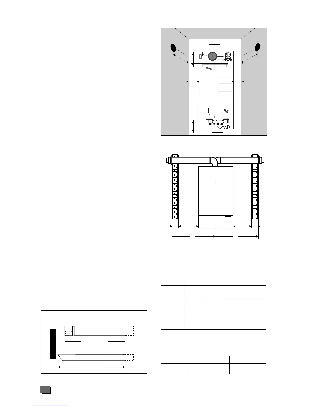
FLUE INSTALLATION
The boiler is only suitable for top outlet flue
connection.
A - Flue to rear of boiler
● Mark correct position of hole from template.
B - Flue to side of boiler
● Mark the horizontal centre line for the hole on the
rear wall. Extend the horizontal centre line to the
side wall and mark the vertical centre line of flue
hole as shown in diagram 13.
Under normal circumstances, it will be possible to gain
access to the outside of the building to fit the flue
terminal assembly. Where outside access is not pos-
sible e.g. high rise buildings, the flue terminal can be
fitted from inside the building only if required.
Important : When cutting the flue hole and when
extending the flue centre line to a side wall,
remember that the flue system must have a fall of
about 35 mm per metre of flue DOWNWARD
TOWARDS the boiler. There must NEVER be a
downward incline towards the terminal.
Cutting the flue hole
● Making allowance for the slope of the flue, cut
hole in external wall, preferably using a core drill.
For installations with internal and external access -
Use a 105 mm diameter core drill.
For installations with internal access only - Use a 125
mm diameter core drill.
Important : Before cutting the hole for flues to the
rear of boiler, always cover fixing jig to make sure it
is not damaged.
Calculation of flue cutting lengths
● Measure wall thickness e (mm), see diagram 14.
● For side flues, measure distance from inside face
of side wall to centre line of flue and subtract 293
mm for right hand flue or subtract 227 mm for left
hand flue to get dimension a (mm).
● Refer to table 1 for cutting lengths of both inner
and outer flue pipes for each of the various flue
options available.
Important : All flue cutting lengths must be measured
from the terminal end of the flue pipes, see diagram
15.
When the dimension X measured on site is greater
than that given in table 1, a flue extension kit will be
required, refer to table 2 for details.
Ven 089a
Cutting length
Cutting length
Outer pipe
Inner pipe
Terminal end
Ins 033AT
Flue option Dimension "X" N° of
extension kits
Side flue 756 to 1756 mm 1
left or right 1757 to 2757 mm 2
Table 2
Flue option Cutting length (mm) Comments
outer pipe inner pipe
Rear flue e + 196 e + 271 maximum wall
thickness "e" without
extension 554 mm
Side flue left e + a + 222 e + a + 297 maximum
distance "X" without
extension 755 mm
Side flue right e + a + 288 e + a + 363 maximum
distance "X" without
extension 755 mm
Table 1
Hab 210b
ee
a
a
X
X
Diagram 14
Diagram 13
Diagram 15