Multistat Smart Thermostat Deployment Guide (CLI-W210x/W200x) 6 of 21 45 Perseverance Way, Hyannis MA 02601
009-1959-00 | 200723 Savant.com | 508.683.2500
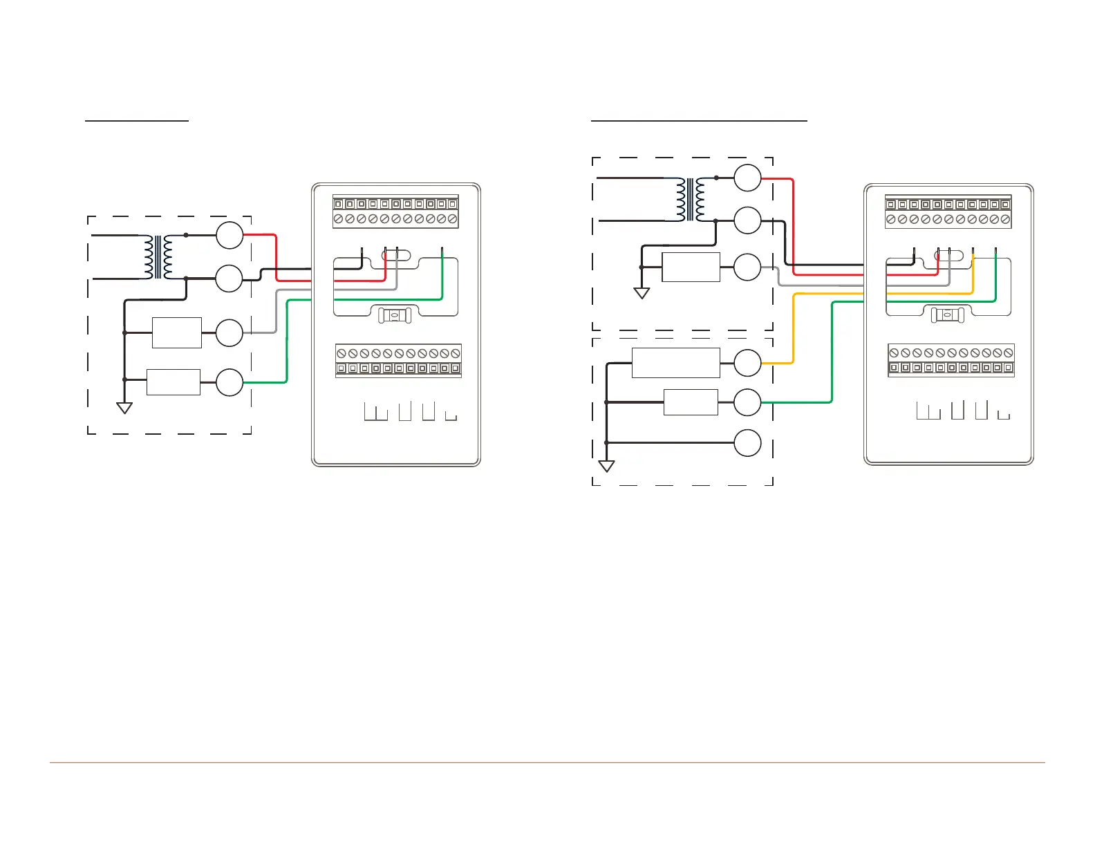
4. Wiring Diagrams
Use the diagrams below when wiring the various types of HVAC systems.
1 Stage Heat
o
G
AUX OUT
AUX IN
RS2
RS1
GND
GND
RX-
RX+
GND
1-WIRE
5V DC
Y2
Y1
W2
W1
RC
RH
TX+
TX-
24C
120V AC
C
R
W1
24V AC
FURNACE CONNECTIONS
Fan Relay
G
1st Stage
Heat
– Connect 24V AC to the RC and 24C terminals.
– Leave jumper shunt JP1 on the electronics board installed.
– Connect W1 from the thermostat to W1 (stage 1 heat) in the HVAC
system.
– Connect G from the thermostat to the fan terminal in the HVAC
system.
– Savant recommends using standard #18 AWG HVAC wiring.
1 Stage Heat, 1 Stage Cool
o
G
AUX OUT
AUX IN
RS2
RS1
GND
GND
RX-
RX+
GND
1-WIRE
5V DC
Y2
Y1
W2
W1
RC
RH
TX+
TX-
24C
C
W1
1st Stage
Heat
24V AC120V AC
FURNACE CONNECTIONS
AIR CONDITIONER
CONNECTIONS
Compressor
1st Stage
Fan Relay
R
G
Y1
C
– Connect 24V AC to the RC and 24C terminals.
– Leave jumper shunt JP1 on the electronics board installed.
– Connect W1 from the thermostat to W1 (stage 1 heating) in the HVAC
system.
– Connect Y1 from the thermostat to Y1 (stage 1 cooling) in the HVAC
system.
– Connect G from the thermostat to the fan terminal in the HVAC
system.
– Savant recommends using standard #18 AWG HVAC wiring.