Programming parameters and settings 8 -
Doc.nr : )HO7DOHWNDQLQWHUHSUHVHQWHUDVLDQJLYHWIRUPDW
8
',QGLYLGXDOGHOD\VIRUVWRS
PRYHPHQWV
Stop delay
, i.e. the time required for the manoeuvre valve slide to return to its neutral position
from when the manoeuvre lever is returned to its neutral position. Times can be set
individually to between 0 and 5 seconds for A and B ports. 6HHWDEOH
( 0 = no stop delay i.e.
normal delivery state, 15 = maximum stop delay ).
([DPSOH
After installation and test running it is found that the 3rd and 5th lever/movement
stop speeds need to be delayed for A or B ports. Below is shown how a stop delay is
programmed for the 3rd lever manoeuvres of 0.3 secs for the A port and 0.6 secs for the B
port. See table: No. 3 = 0.3 secs (A port) and No. 6 = 0.6 secs (B port).
'2$6)2//2:6
1. Remove thebattery pack. Connect the cable between the control unit and electronicbox and
test run the crane. Then press the emergency stops on the control unit and the crane.
2. Twist up the emergency stop on the control unit and on the crane.
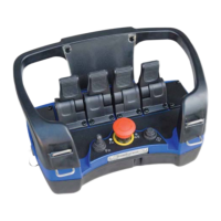
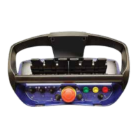
3. Press the control unit’s ON/SIGNAL/FREQ.-SHIFT button.
7KHUHG/('VKRXOGOLJKWFRQWLQXRXVO\
4. Produce impulses in very quick succession
with spring return switch MICRO to RIGHT in
the2))GLUHFWLRQuntil the control unit gives a long beep signal. Wait approx. 12 seconds
until the next long beep signal then continue with item 5.
Note 1. The red LED will be extinguished each time the control unit gives a beep signal.
Note. 2.
If you do not receive the first long beep signal, start again from item and execute items . and .
quicker. Items . and . must be executed within max. 5 seconds
.
5. Now press ON/SIGNAL/FREQ.-SHIFT six (6) times.
7KHFRQWUROXQLWVEXLOWLQEHHSHUZLOOJLYHRQHORQJDQGWZRVKRUWEHHSVRQFHHYHU\VHFRQGVWRFRQILUP
WKDWWKHLWHPVDERYHKDYHEHHQGRQHFRUUHFWO\,IDQ\RWKHUEHHSVLJQDOVDUHKHDUG\RXPXVWUHVWDUWIURPLWHP
DJDLQ
Now you can easily change the stop delays for A and B ports, see item 6.
6. Now operate the crane. Move the 3rd manoeuvre lever just enough to start the crane
moving in for example the A direction. Give switch MICRO three (3) impulses to the
LEFT LQWKH21GLUHFWLRQDVWDUWGHOD\RIVHFVZLOOQRZEHSURJUDPPHG1R VHFV.
Move the 5th manoeuvre lever to just enough to start the crane moving for example in the B
direction. Give switch MICRO six (6) impulses to the LEFT LQWKH21GLUHFWLRQ DVWDUW
GHOD\RIVHFVZLOOQRZEHSURJUDPPHG1R VHFV.
When you run the crane you may find that you still want to change/adjust a time (see table).
Do as follows:
Give the MICRO switch impulses to the RIGHT, towards ON, to decrease times or to the
LEFT, towards ON, to increase times for the levers. ( One impulse equals one step in the
table ).
Run the crane and check that the start delays are as desired.
7. Press the emergency stop on the CONTROL UNIT.
Programming is now completed and the crane is operating with the speeds YOU decided in
item 6. If you are not satisfied with any of the start delays repeat programming - see item 1.


 To Next Page
 Loading...