Programming parameters and settings 8 -
Doc.nr : )HO7DOHWNDQLQWHUHSUHVHQWHUDVLDQJLYHWIRUPDW
10
&RQWUROXQLW
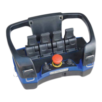
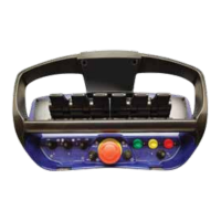
The portable control unit, which is design registered, can be provided with up to eight
( 8 )
manoeuvre levers and is impact resistant and weather resistant with low weight and ergo-
nomic design. The manoeuvre levers can give fully variable operation and are sprung loaded
to return to the neutral position, i.e. "dead-man’s-handle". The speed of the crane is directly in
proportion to the manoeuvre lever displacement. For maximum safety there is a neutral
position control on the manoeuvre levers, and they have also been given a separate neutral
position circuit which disconnects the manoeuvre lever within an area of approx. ± 3° from
the manoeuvre lever’s neutral position. All manoeuvre levers are protected by a protective
frame against unintentional manoeuvring and against mechanical damage. The control unit
has an emergency stop which immediately stops all crane movement. The control unit has
micro operation as standard
, i.e. the speed can be reduced temporarily in five steps to 60%,
50%, 40%, 30% and 20% of normal crane speed. Full movement of the levers is still used for
the reduced speed control. The battery is located in the control unit and can be very easily
changed. The radio transmitter and its antenna are built in. A LED and sound signal indicate
operational and battery status and are used for easy diagnostic fault finding. The control unit
can be equipped with a large number of toggle switches for ON/OFF functions such as :
starting and stopping of the vehicle motor, throttle control ( RPM+/-, fast, automatic* )
*DXWRPDWLFWKURWWOHFRQWUROLHWKURWWOHRSHQLQJWDNHVSODFHDWWKHVDPHWLPHWKDWDPDQRHXYUHLVVWDUWHGZLWK
DQ\RIWKHOHYHUV&ORVLQJRIWKHWKURWWOHLVGHOD\HGLHLWUHPDLQVRSHQIRUDSSUR[VHFRQGVDIWHUWKHODVW
OHYHUPRYHPHQW ),
a switch which enables the number of functions in the control unit to be
doubled etc. The control unit is supplied with a strap to enable it to be hung around the neck
( a waist belt is available as an option ).
2SWLRQ,QGLFDWLRQRQWKHSRUWDEOHFRQWUROXQLW
The control unit can easily be provided with a display and LEDs for indication and reading of values
from the crane : the actual weight being lifted, indications of 60% to 90% loading ZDUQVWKHGULYHU
LQJRRGWLPHZKHQWKHOLPLWIRUWKHFUDQHVOLIWOLPLWLVFORVH ), 100% loading LQGLFDWHVWKDWWKHOLPLW
IRUWKHFUDQHKDVEHHQH[FHHGHG ), indication of instability in the vehicle (ZDUQVWKHGULYHUZKHQWKH
FUDQHLVJHWWLQJFORVHWRWKHGULYHUVFDEZKHUHVWDELOLW\RIWHQLVQRWVXIILFLHQW ), indication of so
called increased lifting power.HJ3DOILQJHUV+3/6)DVVLV;3+0)V+'/HWF
(OHFWURQLFER[DQGFRQWUROV\VWHP
The remote control system can be mounted onto all hydraulic valve types available on the
market. Remote control makes it possible to pre-set speeds individually for each function. All
desired programming-/ calibration of the manoeuvre characteristics can be made during
operation ( on-line ). Programming is easy and requires neither tools/instruments nor any
special knowledge. The powerful PLC in the control system is supplied with and prepared for
2-way direction communications, signal handling of for example ramp, blocking, hold,
overload functions and the field bus CAN-BUS e.t.c.
7KHV\VWHPLVGHYHORSHGDQGPDQXIDFWXUHGHQWLUHO\E\XV
Scanreco Industrielektronik AB
Box 47144 / Årsta Skolgränd 22
S-100 74 Stockholm
Tel : +46 8 556 32 800
Fax : +46 8 556 32 828
E-mail : scanreco@scanreco.se


 To Next Page
 Loading...