16
2017-12-21 / V1.3
Connectors Series M – Installation and Maintenance Instructions
Cable Assembly and Processing
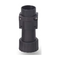
Plugs / receptacles with ange for wall
assembly
X
Slide the cable from the rear through the mount-
ing wall (8).
X
Thread the plug / receptacle with ange (9) on the
cable and mount the ange with the fastening
screws on the mounting wall (8) with the prepared
mounting hole.
X
In doing so, also screw on protection cap (10) with
one of the fastening screws on the ange (11).
X
For the assembly use
- M3 screws for M1 series,
- M4 screws for M3 series.
The torque for the fastening screws is in both series
2.5Nm.
M1 K15
M3 K35
9
10
8
11
Fig. 9: Example of assembly for ange mount plugs on a
mounting wall (applies also for receptacles with
ange)
Plugs / receptacles with thread for wall
assembly
NOTICE
Loctite 5331 threadlocker is to be used for the plugs/
receptacles with thread for wall assembly.
X
Slide the cable from the rear through the mount-
ing wall (12).
X
Thread the protection cap (14) on the thread side
onto the plug/receptacle (13).
X
Thread the plug/receptacle with thread (13) onto
the cable.
X
Apply Loctite 5331 to the thread (15) and screw
the plug/receptacle into the mounting wall fur-
nished with the same thread.
The torque for all receptacles with thread is 2.5 Nm.
For the assembly of the contacts and contact inserts
refer to section „6.6 Assemble Contacts into Contact
Inserts“ und „6.8 Assemble Contact Inserts into Recep-
tacle / Plug shells“.
13
14
12
15
Fig. 10: Example of assembly for receptacles with thread on a
mounting wall (applies also for plugs with thread)
6.5 Make Crimp Connections
The connection of the crimp contacts has to be made
according to DIN EN 60352-2 – Solderless Connections.
In order to comply with DIN EN IEC 61984 make sure that
always the live side of the connector – no matter wheth-
er plug or receptacle – is tted with socket contacts.
For all contact inserts observe the following:
- for pin inserts a socket contact must be used for the
protective earthing (PE) contact,
- for socket inserts a pin contact must be used for the
protective earthing (PE) contact.
Assembly
X
Disengage the cable at the connection end from
the coating and strip cable strands approx. 7 mm.
X
Push the cable strands into the contacts.
X
Crimp the cable strands to the contacts using the
crimping pliers.
- In doing so, observe connection cross-section
of contacts depending on the model of the
crimp contacts (refer to section “6.2 Crimp con-
tacts (pin / socket) and ller plugs”).
- Crimping must be made in the centre between
the sight drill hole and the end of the contact.
7 mm
Fig. 11: Skin cable strands and crimp to contacts.