23
2017-12-21 / V1.3
Connectors Series M – Installation and Maintenance Instructions
Plugging Procedure
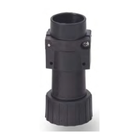
Fig. 26: Screw union nut (5) on thread of receptacle
X
Check that the connector is connected correctly.
For this purpose, control the gap between union
nut and receptacle shell on the basis of the nomi-
nal sizes indicated in the following table.
Type of re-
ceptacle
Nominal sizes for the gap between
union nut and receptacle shell when
the connection is correctly screwed
M1 M3
Cable re-
ceptacles
Receptacles
with ange
Flange
mount
angled
receptacles
approx. 10 mm
Receptacles
with thread
Receptacles
for shrink
boot
---
7.2 Unplugging
X
Screw o the union nut (5) of the plug (3) from the
receptacle (4) and take o the plug.
X
Close plug and receptacle with the protection
caps, refer to „7.3 Attach Protection Caps“.
Fig. 27: Screw o union nut (5)
Fig. 28: Slide o plug (3) from receptacle (4)
7.3 Attach Protection Caps
In order to meet the requirements of the protection
class and to prevent the connectors against the entry
of dirt or moisture, make sure that plugs and recepta-
cles, when not mated, are always closed with protec-
tion caps.
X
Make sure that the protection caps are free of dirt
and deposits.