20
2017-12-21 / V1.3
Connectors Series M – Installation and Maintenance Instructions
Cable Assembly and Processing
Assembly
X
Insert the completely wired contact insert (1) in
desired coding position (A or B) with the grooves
into the guideways of the shell (2) and push the
contact insert into the shell.
X
Put on tting insertion tool (3) and press the
contact insert downwards in an axial direction
up to the detectable mechanical stop (4-1). (This
equates to overriding the corrugated spring up to
the mechanical stop.)
X
In this pressed position, turn the contact insert in
a clockwise direction to the nal position (4-2).
X
Bring the insertion tool out in this position.
The contact insert is then pushed up by the cor-
rugated spring up to the stop.
1
2
3
4
45°
Fig. 19: Assemble contact insert into the shell
using the insertion tool
Check
X
Check if all contact inserts are locked correctly and
properly in place.
Disassembly
X
Put on tting insertion tool (3) and press the con-
tact insert downwards in an axial direction up to
the detectable mechanical stop. (This equates to
overriding the corrugated spring up to the me-
chanical stop.)
X
In this pressed position, turn the contact insert an-
ticlockwise up to the mounting position.
X
Bring out the insertion tool together with the con-
tact insert in this position.
6.9 Final Assembly of the Connectors
After the completely wired contact inserts have been
assembled into the receptacle / plug shell and have
been checked whether they are locked correctly and
properly in place, the nal assembly of the connectors
may be made.
The following illustrations show for some examples of
application how the nal assembly of the connector
parts is made.
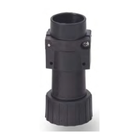
Final assembly of cable plugs / cable
receptacles
X
Push the cable sleeve (8) into the shell (9).
X
Screw together the strain relief (7) with the plug /
receptacle shell (9).
X
Accomplish the strain relief by tightening the two
screws (5). Tightening torque: 2.5 Nm
X
Attach the protection cap (10) to the plug / recep-
tacle shell (9) and screw down the cap.
5
9
10
6 7 8
Fig. 20: Example for cable plugs with back shell, strain relief
and cable gland (applies also for cable receptacles)
 Loading...