19
2017-12-21 / V1.3
Connectors Series M – Installation and Maintenance Instructions
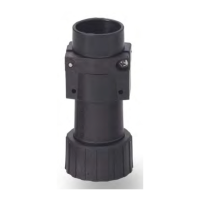
Cable Assembly and Processing
In the following table, the coding positions A and B are
illustrated for the dierent contact inserts. The illustra-
tions refer respectively to the mounting position of the
corresponding contact insert.
During assembly, the contact inserts must be pressed
downwards in an axial direction into the housing with
the tting insertion tool up to the detectable mechani-
cal stop. (This equates to overriding the corrugated
spring up to the mechanical stop.)
In this pressed position, turn the contact insert in a
clockwise direction to the nal position.
The insertion tool must be brought out in this position.
The contact insert is then pushed up by the corrugated
spring up to the stop.
Coding position A
Coding position B
(rotated by 90° from coding position A)
Pin inserts Socket inserts Pin inserts Socket inserts
Series M1
A
B
1
2
3
4
PE
45°
Mounting
position
Final position
M1 E-4P+PE
1
2
3
4
PE
45°
Mounting
position
Final position
A
B
M1 E-4S+PE
B
1
2
3
4
PE
45°
Mounting
position
Final position
M1 E-4P+PE
Mounting
position
1
2
3
4
PE
A
B
M1 E-4S+PE
1
5
6
2
3
4
PE
Mounting
position
Final position
A
B
M1 E-6P+PE
1
5
6
2
3
4
PE
Mounting
position
Final position
A
B
M1 E-6S+PE
1
5
6
2
3
4
PE
Mounting
position
Final position
A
B
M1 E-6P+PE
Mounting
position
Final position
1
5
6
2
3
4
PE
A
B
M1 E-6S+PE
Series M3
2
3
1
5
6
4
PE
Mounting
position
Final position
A
B
M3 E-6P+PE
2
3
1
5
6
4
PE
45°
Mounting
position
Final position
A
B
M3 E-6S+PE
2
3
1
5
6
4
PE
45°
Mounting
position
Final position
A
B
M3 E-6P+PE
Mounting
position
Final position
2
3
1
5
6
4
PE
A
B
M3 E-6S+PE
Mounting
position
Final position
1
2
6
7
8
5
4
PE
3
M3 E-5P+3P+PE
1)
Mounting
position
Final position
1
2
6
7
8
5
4
PE
3
M3 E-5S+3S+PE
1)
Mounting
position
Final position
1
2
6
7
8
5
4
PE
3
M3 E-5P+3P+PE
1)
Mounting
position
Final position
1
2
6
7
8
5
4
PE
3
M3 E-5S+3S+PE
1)
1
5
6
4
7
10
11
12
92
3 8
PE
Mounting
position
Final position
A
B
M3 E-12P+PE
1
5
6
4
7
10
1112
9
2
3
8
PE
Mounting
position
Final position
A
B
M3 E-12S+PE
1
5
6
4
7
10
11
12
92
3 8
PE
Mounting
position
Final position
A
B
M3 E-12P+PE
Mounting
position
Final position
1
5
6
4
7
10
1112
9
2
3
8
PE
A
B
M3 E-12S+PE
1
5 6
4
7
10
11
14
12
13
9
2
3
8
PE
Mounting
position
Final position
A
B
M3 E-7P+7P+PE
1
5
6
4
7
10
11
14
12
13
9
2
3
8
PE
Mounting
position
Final position
A
B
M3 E-7S+7S+PE
1
5 6
4
7
10
11
14
12
13
9
2
3
8
PE
Mounting
position
Final position
A
B
M3 E-7P+7P+PE
Mounting
position
Final position
1
5
6
4
7
10
11
14
12
13
9
2
3
8
PE
A
B
M3 E-7S+7S+PE
1) Note: For the contact inserts M3 E-5P+3P+PE and M3 E-5S+3S+PE, the designations of the coding positions “A”
and “B” are not printed on the contact insert.