21
2017-12-21 / V1.3
Connectors Series M – Installation and Maintenance Instructions
Cable Assembly and Processing
Only for shells M11 Z, M16 Z, M31 Z, M36 Z:
In order to achieve an additional protection against
twisting for the strain relief (7), 2 self-tapping screws
may be screwed into the prepared drill holes (6) (the
screws are not part of the shipment):
- for the shells M11 Z, M16 Z two self-tapping screws
with cylinder head 2.2 x 9.5 are needed for this.
- for the shells M31 Z, M36 Z two self-tapping screws
with cylinder head 2.9 x 13.
The tightening torque for the self-tapping screws is
2.5Nm.
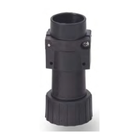
Final assembly of plugs / receptacles with
thread
X
Insert the O-ring (4) into the back shell (3).
X
Screw together the back shell (3) with the plug / re-
ceptacle shell (6).
X
Push the strain relief with the rubber ring (2) into
the back shell (3).
X
Screw together the cable gland (1) with the back
shell (3).
X
Attach the protection cap (5) to the plug / recepta-
cle shell (6) and screw down the cap.
2
1 3 4 6
5
Fig. 21: Example for plug with thread, back shell and cable
gland (applies also for receptacles with thread)
Final assembly of plugs / receptacles with
thread and 90° shrink boot
X
Push the shrink boot (7) onto the plug / receptacle
shell (6) and shrink with the shaft of the shell.
X
Attach the protection cap (5) to the plug / recepta-
cle shell (6) and screw down the cap.
7
6 5
Fig. 22: Example for plug with thread and 90° shrink boot (ap-
plies also for receptacles with thread)
 Loading...