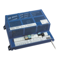
Operating Instructions Caravan-charging system CSV 416
8
Date: 30.05.2021 8050111 BA / EN
A bus-compatible control panel must be connected for operation.
Connections provided for:
F Bus devices
F T wo tank sensors
F Solar charge regulator (optional)
Flat vehicle fuses protect the various circuits.
F Excess temperature
F Overload
F Short circuit
230V AC 10%, 47 -- 63 Hz sinusoidal, protection class I
12V outputs may only be loaded up to a maximum of 90% of the rated
current of the associated fuse (see block diagram or nameplate).
All consumers together may not exceed the following load:
F Mains operation: 28 A
F Operation with towing vehicle, ignition ON: 8 A
4.1 Battery functions
Lead-acid, lead-gel, AGM (1/2) or lithium batteries from 80 Ah
Charging the caravan battery whilst driving; increasing the supply voltage
coming from the towing vehicle via the battery booster
Maximum charging current 8 A
Caravan battery
Characteristic charging curve IUoU
Final charging voltage Dependent on
battery type (see Section 6)
Charging current 28 A
Voltage for trickle charge Dependent on
battery type (see Section 6)
The main 12V switch on the control panel connected isolates most 12V
consumers from the caravan battery (see also Page 5).
This prevents the caravan battery from being slowly discharged by standby
currents.
The batteries can continue to be charged by the caravan charging system,
the towing vehicle or the solar charge regulator (if available), even when the
main battery switch is OFF.
Actuation
Protective circuits
Mains
Current
Batteries
Battery charging when
vehicle is moving
Battery charging for
mains connector
12V main switch