Installation Instructions Solar systems (controller and panel)
5
Date: 20.09.2018
9990314 MA / EN
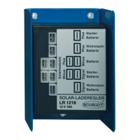
Solar regula-
tor
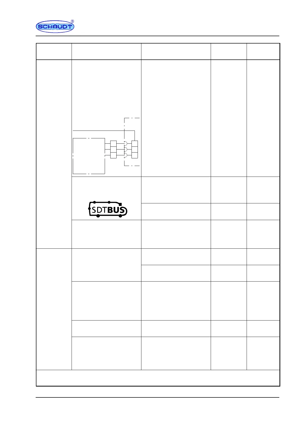
SeeBus systemDisplayConnectiontobattery
LRM 1218 Via EBL with 3-pin
connection, 2 pins assigned;
the following solar regulator
connector is in the block
diagram (E is either not
assigned or routed in the
EBL to an input for a solar
module); A is used here as
an input for the leisure area
battery:
to LR(M) solar charge regulator
[-- ]
[+]
(E)
Solar
3F MNL socket
A (LAB)
Negative
charge regulator
3
1
2
3
1
2
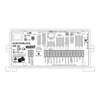
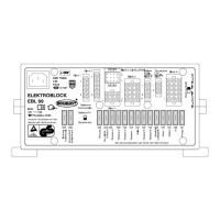
EBL ...
Via LT 320 -- Section
5.3
Via bus-compatible EBL; the
following symbol might be on
the front panel:
Via bus panel with solar
power display
SDT 213 Section
7.2
Via LT 320* SDT 630
SDT 213
Section
7.3
Directly on the vehicle for
third party systems or EBLs
without solar regulator con-
nector
LT 320 -- Section
5.1
LR 1218 Via EBL with 3-pin connector
(EBL connection diagram as
LT 320 -- Section
5.2
for
RM 1218; see above).
Display panel with solar
power display, e.g.
-- Section
5.4
Via EBL with 3-pin
connector, 2 pins assigned
(EBL connection diagram as
for LRM 1218; see above).
LT 320 -- Section
5.3
Directly on the vehicle for
third party systems
LT 320 -- Section
5.1
Via bus-compatible EBL;
symbol specified as for LRM
1218
Via LT 320 SDT 630
SDT 213
Section
7.1
* Dual display of solar power in Normal mode; but display option also for active shutdown. Refer to Section
7.3.
 Loading...