english 21
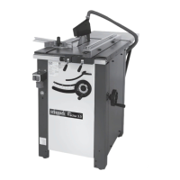
Setting into operation
Pleasereadthesafetyinstructionsbeforesettingthesaw
bench into operation.
Allprotectiveandauxiliarydevicesmusthavebeenmount-
ed.Theisreadyforoperationwhenithasbeenconnectec
tothemains.NOTE:Inaccordancewithvalidproductli-
abilitylaws,themanufacturerofthisdeviceshallnotbe
responsiblefordamagetoandfromthisdevicewhichre-
sults from:
• Impropercare
• NoncompliancewiththeOperatingInstructions
• Repairsmadebyunauthorizedpersons
• Theinstallationanduseofanypartswhicharenotorigi-
nal replacement parts.
• Improperuseandapplication
• Failureoftheelectricalsystemasaresultofnoncompli-
ancewiththelegalandapplicableelectricaldirectives
andVDEregulations0100,DIN57113/VDE0113
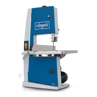
Sawblade height adjustment – Sawblade angle adjustment, Fig. H
• The height adjustment ismade by therotation ofthe
wheelonthefrontofthemachine(1).
-SawbladeØ280mm=heightofcutfrom0to90mm
at 90 ° and 0 to 68 mm at 45 °
•Foradjustingthesawbladeanglesettingpulloutthe
handwheelontherightsideofthemachine(2)
- Tilting the blade from 90 ° to 45 °.
-Oncetheadjustmentmade,tightenthegripblocking(3).
Parallel guide, Fig. J, J1, J2
Fine-adjustmen
Fineadjustmentiswiththeadjustingspindle(3)withthe
eccentriclever(1)isblockedandtheeccentriclever(2)
is open.
Stop rail
Position 1 (Fig. J1):Forworkingwithraisedstopbarsur-
face.Thedispayedcutwidthisontheblackdisplayscale
(1).(Higherstopbarsurfacesymbol)
Position 2 (Fig. J2):Forworkingwithloweredstopbarsur-
face. Thedispayedcutwidthisontheblackdisplayscale
(1).(Lowerstopbarsurfacesymbol)
Push-stick and push-grip
Push-stick:Whencuttingnarrowworkpieceslengthwise(i.e.
smallerthan120mm),itisessentialtousethepush-stick.
Push-grip:Whencuttingsmallworkpiecesofspecialform,
it isessential to use the push-grip.
Mitre guide, Fig. G, Fig. G1
Setthemitreguideastherightorleftofthesawblade.
The mitre guide can be directed angle of -45° to +45°.
Refertograduatesector.
Locking fence, Fig. G2(specialaccessory)
The locking fence mounted on the mitre guide is a perfect
complementtomakelengthcutswiththemitreguide.
Changing the sawblades, Fig. F, Fig. F1, Fig. F2
IMPORTANT! Only use sharp, tear-free, unde-formed ‘‘origi-
nalscheppachsawblades’’.
Caution:
When changing the sawblade take out the mains plug!
1 Holding mandre
2 Left-handed hexagonale nut M24
• Takeouttheleft-handtableinlay(Fig.F1)
• Inserttheholdingmandrel(1)intothesawspindlethr-
pough(Fig.F2) theborein theright-handside ofthe
table. For releasing or tightening up the hexagonal nut
M24the saw spindleislocked with theholdingman-
drel.
• Makenoteoftherunningdirectionofthesawblade.
Riving knife, Fig. F
Releasethescrew(1),insertandclampintherivingknife.
Thedistancebetweenthesawbladeandtherivingknife
must amount to no more than 8 mm and must be checked
eachtimethesawbladeischangedandresetasnecessary.
Therivingknifetipmustneverbesetlowerthantheheight
ofthebaseofthetopmostsawtooth.Asttingtomax.2mm
underthetopmostsawtoothtipisideal.The riving knife
is an irnportant safety device, which guides the workpiece
and prevents the cut pinching and the workpiece being
thrown backwards. Note the riving knife thicknessrefer to the
nurnbers starnped on the riving knife. The riving knife must
not be thinner than the sawblade body and not thicker than
its cutting joint width.
Attention! Close the protection cap
Risk of damage!
Maintenance
Always switch off the motor and disconnect the plug from the
power supply prior to any maintenance and cleaning work.
The following maintenance points should be checked on the
circular saw blench.
• Checkthebelttensionafterapproximatelyoneoperating
hour; retension if necessary. For this purpose open the up-
persidewall.Byuniformadjustmentofthefasteningnuts
on the motor, adjust the necessary belt tension.
Afterthisrstinitialadjustment,checkthebelttensionat
regular intervals.
• Occasionally,oiltherollerchainandmovingparts(height
andangleadjustment).Openthetoprightsidewall.
• Ensurethatthebenchsurfaceisalwaysfreeofresin.
• Thesawprotectionboxmustbeclearedoccasionallyof
woodshavingsandsawdustsothatshavingsdonotjam
whenejected.
• Theheightandangularadjustmentareamaybereduced
byshavingdeposits.Removetheleftbenchinlayandclean
the adjustment area.