20 english
• Thecircularsawbenchisdesignedexclusivelyforthema-
chiningofwoodandmaterialssimilartowood.Onlyoriginal
toolsandaccessoriesmaybeused.Usetherequiredsawb-
ladeinaccordancewiththeEN847-1normdependingon
thetypeofcutandtypeofwood(solidwood,plywoodor
chipboard).Pleaseobservethe„SpecialToolAccessories“.
Remaining hazards
The machine has been built using modern technology in ac-
cordancewithrecognizedsafetyrules.Someremaininghaz-
ards,however,maystillexist.
• Therotatingsawbladecancauseinjuriestongersand
handsiftheworkpieceisincorrectlyfed.
• Thrownworkpiecescanleadtoinjuryiftheworkpiece
isnotproperlysecuredorfed,suchasworkingwithouta
limit stop.
• Noisecanbeahealthhazard.Thepermittednoiselevel
isexceededwhenworking.Besuretowearpersonalpro-
tective gear such as ear protection.
• Defectivesaw blades can causeinjuries. Regularly in-
spectthestructuralintegrityofsawblades.
• Theuseofincorrectordamagedmainscablescanlead
to injuries caused by electricity.
• Even when all safety measures are taken, some re-
maininghazardswhicharenotyetevidentmaystillbe
present.
• Remaininghazardscanbeminimizedbyfollowingthe
instructionsin„SafetyPrecautions“,„ProperUse“and
in the entire operating manual.
Mounting
Allassemblyandretrottingworkmayonlybeperformed
whenthemainsplughasbeendisconnected.
Your circular sawbench is not completely assembled for
packaging reasons.
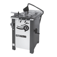
Deliveryofthemachine,Fig.A,Fig.A1
YourcircularsawPrecisa3.0comesinawoodenbox.
IMPORTANT:Forreasonsoftransport,themachineis
deliveredinreverse,ietablesawingdown.
Openwoodenboxstartingwithremovingthelid,then4
sides.
Itemssuppliedstandard,Fig.B
CAUTION:
Some elements are stored in the machine:
•1lenghtextensiontablewithsupportsandscrews
•1 parallel fence
• 1 carton accessories consist of:
- 1 mitre guide
- 1 rule for mitre guide
-1sawbladeguardwithsuctionhose
- 1 push-stick
- 1 push-grip
- 1 holding mandre
-1specialsawbladekey
-1atdouble-endkey SW13etSW17
-1atdouble-endkey SW8etSW10
-1allenkey SW2
-1allenkey SW3
-1allenkey SW4
-1allenkey SW5
-1allenkey SW6
Exitalltheseelementsofthemachine.
Put the machine in the place, Fig. C, C1, C2, C3, C4, C5
Thiscanbedonebyoneperson.Forreasonsofweightof
themachine,werecommendthatyoumakesurethatyou
get help from someone.
Table length extension Fig. D, D1, D2, D3, D4
The2anglebracketstotherearofthecircularsawhousing
screws.Boltthescrewsonlybyhand.
4hexagonalscrewsCHC M8x20
4washers Ø8
Placethe4screwssettingsinthethreadsincludedinthe
angle brackets.
4hexagonalscrewsCHC M8x20
Putthetablelengthextensiononthe2anglebrackets.Put
2washersbetweenanglebracketsandthelengthexten-
siontable.Boltthescrewssharply(Fig.D3)
Adjusting : The table length extensionand the machine
tablemustbeinthesamealignment(atness).
adjustthetablelengthextensiontothesawtableatwith
1precisionrule(Fig.D4).Usethe4adjustmentscrewsto
adjust the table length extension from the table machine.
Aftermakingthisadjustment,boltthe4screwssharply.
Parallel fence, Fig. E
Theparallelguideisassembledupondelivery.Puttingthe
parallel guide up on the support at the front of the ma-
chine table.
Saw blade - Riving knife - Suction hood, Fig. F
The saw blade andthe riving knife aremounted on the
machine.
Suction hood(withsuctionconnection)
Screw the saucer-headscrew M6 x40 with washerinto
the suction hood. Clamp the suction hood securley on the
riving knife.
IMPORTANT!Thesuctionhoodmustbeloweredontothe
workpieceforeachnewjob.
Mitre guide, Fig. G
Themitreguideispartiallyassembled.Withtheovalhead
screwandwing-nut,mounttheruleontothemitreguide.
Setthemitreguideastherightorleftofthesawblade.
The mitre guide can be directed angle of -45 ° to +45 °.
Refertograduatesector.