Initial Setup and Use
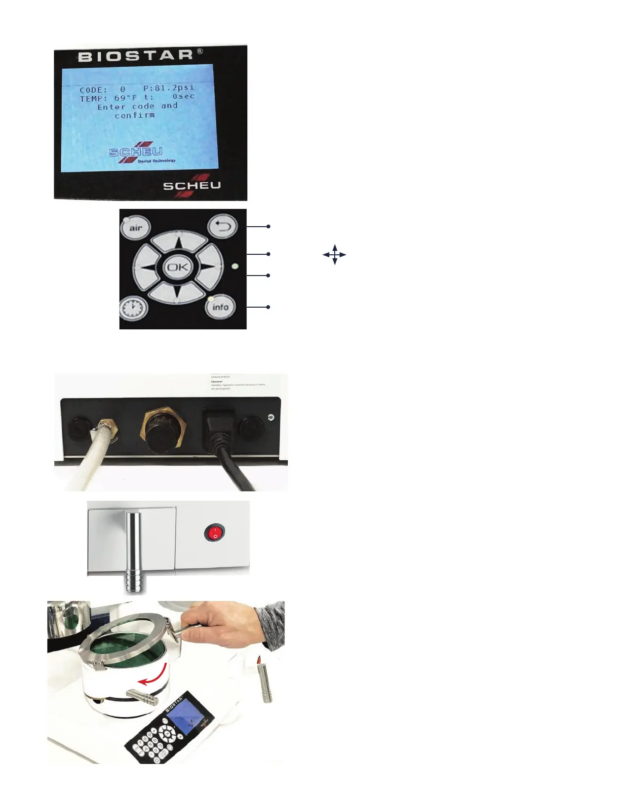
CODE:
Three-digit code to identify heating and
pressure-molding times
t (Heating Time):
Total time to heat the material being used
TEMP:
Actual temperature of the heating lamp
P (Pressure):
Operating air pressure appears on screen
above time and temperature. Measurement
is in psi. Suggested operating pressure is
80psi.
LCD Display Screen
1. Plug the appropriate end of the electrical cord in
the back of the Biostar (A) and the opposite end into
a three-prong 110v outlet. The fuses are located in the
back of the machine to the left of the air hose and to
the right of the electrical connection (B).
(2 Fuses: 5x20mm 10amp)
2. Connect the Biostar to the air source using the
high-pressure hose. Slip one end of the hose onto the
air valve (C) of the Biostar, and slip the other end over
the air pressure line. Secure each end in place with a
hose clamp.
Note: Route the electrical cord and pressure hose
away from the heating element.
3. Turn the power to ‘ON’ position. The red power
switch (D) is located on the lower right corner on the
front of the Biostar.
4. Secure the Clamping Frame (E) to the pressure
chamber by referencing the clamp handle at a 4-5
o’clock position over the chamber. Slip the clips of
the clamping frame in to the grooves on the
outside of the chamber, and slide the clamping
handle to the left (curved red arrow).
D
Use the tabs to navigate through the information menu.
C
B
B
A
Returns to previous page displayed in the main menu.
Press the OK button to select a menu item.
Info button lists items such as safety, indication,
troubleshooting, foils assortment, and videos.
E
E