26
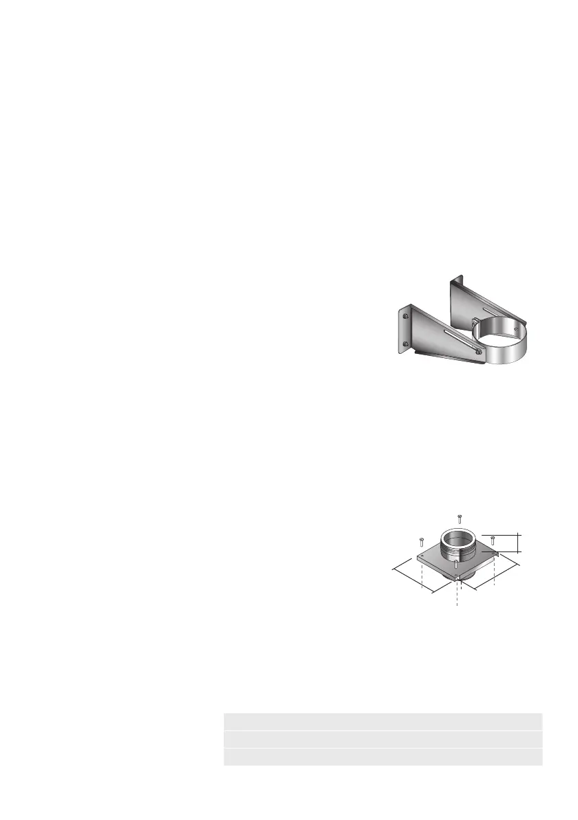
RETROFIT WALL SUPPORT
• Lower the clamp band over the pipe length with the joint facing
the wall.
• On the joint, ensure that the spring washer is between plain
washer and the bolt head,
• Tighten the two fixing bolts on the clamp band using a torque
wrench up to a minimum of 10 Nm (Newton-Meters).
• Attach the side brackets to the fixing bolts on the side of the
band, but don’t tighten.
• Attach the side brackets to the wall using a method of fixing to
ensure adequate attachment and support, i.e. shield anchors.
• Mark up the hole positions for the brackets on the wall.
• Fix the brackets to the bolts on the side of the clamp band using the locking nuts provided.
• For maximum height of chimney see details on p. 40 onwards.
ADJUSTABLE TOP PLATE
The wall support is designed to be used internally or externally
to provide either initial or intermediate support for the vertical
chimney. It is used in combination with side plates or with
cantilever brackets. The turned down edge at the front of the
plates is slotted to allow for the plate to slide along the cantilever
brackets and give some positional adjustment. The female socket
on the pipe attached to the underside of the plate should be
pushed down onto the preceding pipe and the joint secured using
the locking band provided. The top plate is then attached to the side plates or the cantilever
brackets using the bolts provided through the fixing slots in the top plate (see Fig. 1). The bolts
should then be tightened firmly.
For maximum height of chimney see load bearing details, please refer to tables and diagrams on
page 39 and page 40.
Support Components
LOAD BEARING SUPPORTS
All wall supports and oor supports are designed to provide load bearing support for the
chimney. They must be used in combination with the relevant lateral support components,
wall bands, guy wire brackets or telescopic roof stays as appropriate. See p.39 for further
information.
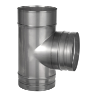
BASE SUPPORT PLATE WITH DRAIN
This component is used to support the chimney directly from the floor. It should be fastened
securely to the floor using bolts or screws provided by others.
Int Ø 80 100 130 150 180 200 230 250 300
A 188 208 238 258 278 285 315 335 385
B 246 266 296 316 346 366 396 416 471
Side Plates
Fig.1 Top Plate