Page 4.17
Chapter 4
Module Removal and Replacement
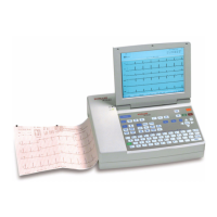
SCHILLER AT-2plus 6-Channel ECG Unit
SERVICE HANDBOOK Issue 1 June 1998
Modem Interface Board MK 14 - 12
Prerequisite
The Warnings and Cautions at the beginning of the Chapter must be observed.
The Top Assembly must be removed as detailed previously. All external cable assemblies
must be disconnected.
Tools
Cross-bladed screwdriver
Part Number
The part number for the Modem board is given in Chapter 6.
CAUTION
THE MODEM BOARD CONTENT IS STATIC SENSITIVE; OBSERVE ANTISTATIC
PRECAUTIONS
Modem board Removal
1. Disconnect the 10 pole connector to the main board.
2. Unscrew the four retaining screws securing the board in position.
3. Remove the board.
Modem board Replacement
To replace the RS-232 board proceed as follows:
1. Position the board and secure at the 4 fixing points.
2. Connect the 10 pole connector to the main board.
3. Reassemble the unit.