Do you have a question about the Schiller AT-10 plus and is the answer not in the manual?
Specifies personnel competencies and adherence to safety instructions.
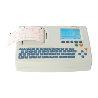
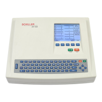
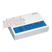
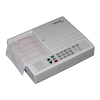
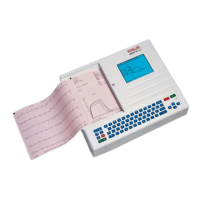
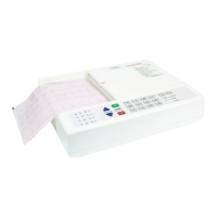
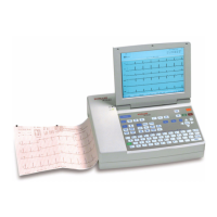
Defines the AT-10 plus as a 12-channel ECG device for diagnostic use.
Ensures proper introduction, accessibility of instructions, and compliance with regulations.
Guidelines for safe operation, avoiding liquids, shocks, and improper cleaning.
Highlights dangers of operating with faulty fuses or cables and electrical safety devices.
Advises using only approved accessories and adhering to IEC standards for connected equipment.
Explains safety levels and symbols like DANGER, WARNING, CAUTION used in the manual.
Outlines the one-year warranty, exclusions, and conditions for maintaining warranty validity.
Details standard features like Pacemaker Detection and optional features.
Lists VGA, DC input/output, RS-232, and SCM module ports.
Explains the different display areas and their information content.
Describes the function of alphanumeric and dedicated function keys.
Details connectors located on the back panel including RS-232, VGA, and power.
Details connectors located on the side panel, including ECG input and RS-232.
Covers location, connecting equipment, potential equalization, and power-up.
Instructions for using the On/Off key to switch the device on and off.
Explains operation from mains or battery, and the corresponding LED indicators.
Describes how to navigate and select options using arrow and confirm keys.
Details electrode resistance check and expected voltage readings for integrity.
Indicates that NIBP tests are not available at the time of print.
Indicates that Spiro tests are not available at the time of print.
Allows display rotation settings and saving them as default.
Explains how to test RS-232 ports using a test plug and observing indicator changes.
Details testing DC In/Out and ERGO ports using test cable and switch.
Allows displaying the complete character set of the unit.
Enables selection of background colour and inversion of the ECG display.
Procedure for checking battery capacity by monitoring printouts after charging.
Steps to check print quality, alignment, and troubleshooting tips.
Provides a table outlining required service intervals and responsible personnel.
A confidence check for main functional areas when a fault is suspected.
Checks mechanical condition, cable integrity, and safety labels periodically.
Verifies the operation of mains and battery indicator lamps and LCD symbols.
Details the procedure for charging the battery for at least 8 hours.
Refers to the service screen for the battery capacity check procedure.
Checks for mechanical damage and verifies all keys function correctly.
Tests for screen spots, black fields, and checks contrast and brilliance.
Covers paper feed, print quality, printing speed, and parallelism tests.
Tests ECG amplifier and patient cable integrity using a simulator.
Compares measured values and waveform shape to a reference table and waveform.
Procedure for setting the unit's language, date, and time.
Instructions for connecting and configuring an external VGA monitor.
Details safety tests according to EN 60601, including leakage current measurements.
Emphasizes using isolation transformers and antistatic precautions.
Step-by-step guide for removing and replacing the unit's battery.
Instructions for changing fuses and adjusting mains voltage settings.
Detailed steps and precautions for safely opening the unit's housing.
Covers internal visual inspection and functional/safety tests after reassembly.
Guidance on cleaning the unit's exterior with a damp cloth and mild cleaner.
Procedure for cleaning and disinfecting the patient cable.
Instructions for cleaning the thermal print head with alcohol to maintain print quality.
Details settings for Pacemaker Detection, Interpretation, Rhythm recording, and filters.
Covers HR target, stage reports, rhythm settings, and QRS parameters for exercise tests.
Includes MTA/User ID, language, date/time, colour, patient data input, and units.
Provides dimensions, weight, power supply, battery, printer, and interface details.
Details ECG input, lead display, filters, automatic programs, and amplifier specifications.
Lists relevant safety and EMC standards (IEC/EN 60601) and protection class.
Illustrates exploded views of the base casing and top/LCD casing.
Presents high-level circuit diagrams like connection block and functional block diagrams.
Describes the fabrication of an RS-232 test plug for interface testing.
Illustrates the DC In/Out cable assembly for testing.
Shows the ERGO connector and switch configuration for testing.
A procedural checklist for authorized personnel to verify unit functionality and safety.
| Display | LCD |
|---|---|
| ECG Channels | 12 |
| Lead System | 12 leads |
| Connectivity | USB, Bluetooth |
| Printing | Thermal printer |
| Data Acquisition | Real-time |
| Filters | Digital filters |
| Power Supply | Rechargeable lithium battery |
| Battery Type | Lithium-ion |
| Operating Temperature | 0 to 50 °C |
| Storage Temperature | -20°C to 60°C |
| Relative Humidity | 10% to 95% (non-condensing) |
| Altitude Range | up to 3000 m |
| ECG Monitoring | Yes |
| Voice Prompts | Yes |