5 Functional Checks
5.3 Functional checks and tests
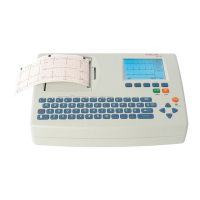
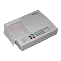
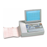
AT-10 plus
Page 38
Art.-no.: 2.540043 Rev.: a
5.3.11 ECG printout reference
1. Connect the simulator to the unit and select the calibrated ECG reference wave-
form EN 60601-2-51 > CAL 20160.
2. Press the Auto Start key to make an auto mode recording printout.
3. Check measurement table (given on the printout) against the following table.
4. Check the waveform and polarity against the reference waveform given on the
following page. Note that the printout is representative of the waveform shape
only and is not accurately scaled.
Reference Table
Required Equipment
• Calibrated test ECG Patient Simulator (e.g Müller & Sebastiani MS410 ECG Sim-
ulator)
If the printout waveform shape does not match the template, check the auto mode set-
tings (see page 51).
Curve Measurement Value Tolerance Minimum Maximum
Interval RR 1000 (ms) + 10 990 1010
P 116 (ms) + 10 106 126
PR 178 (ms) +
10 168 188
QRS 56 (ms) + 6 50 62
QT 356 (ms) +
12 344 386
V1
P 0.15 (mV) + 0.02 0.13 0.17
R2.00 (mV)+
0.1 1.90 2.10
Rd 56 (ms) + 6 50 62
J 0.2 (mV) +
0.02 0.18 0.22
ST 0.2 (mV) + 0.02 0.18 0.22
T 0.4 (mV) +
0.03 0.37 0.43