Page 65
Construction Drawings 10
AT-10 plus Service Handbook Circuit and functional illustrations 10.2
Art.-no.: 2.540043 Rev.: a
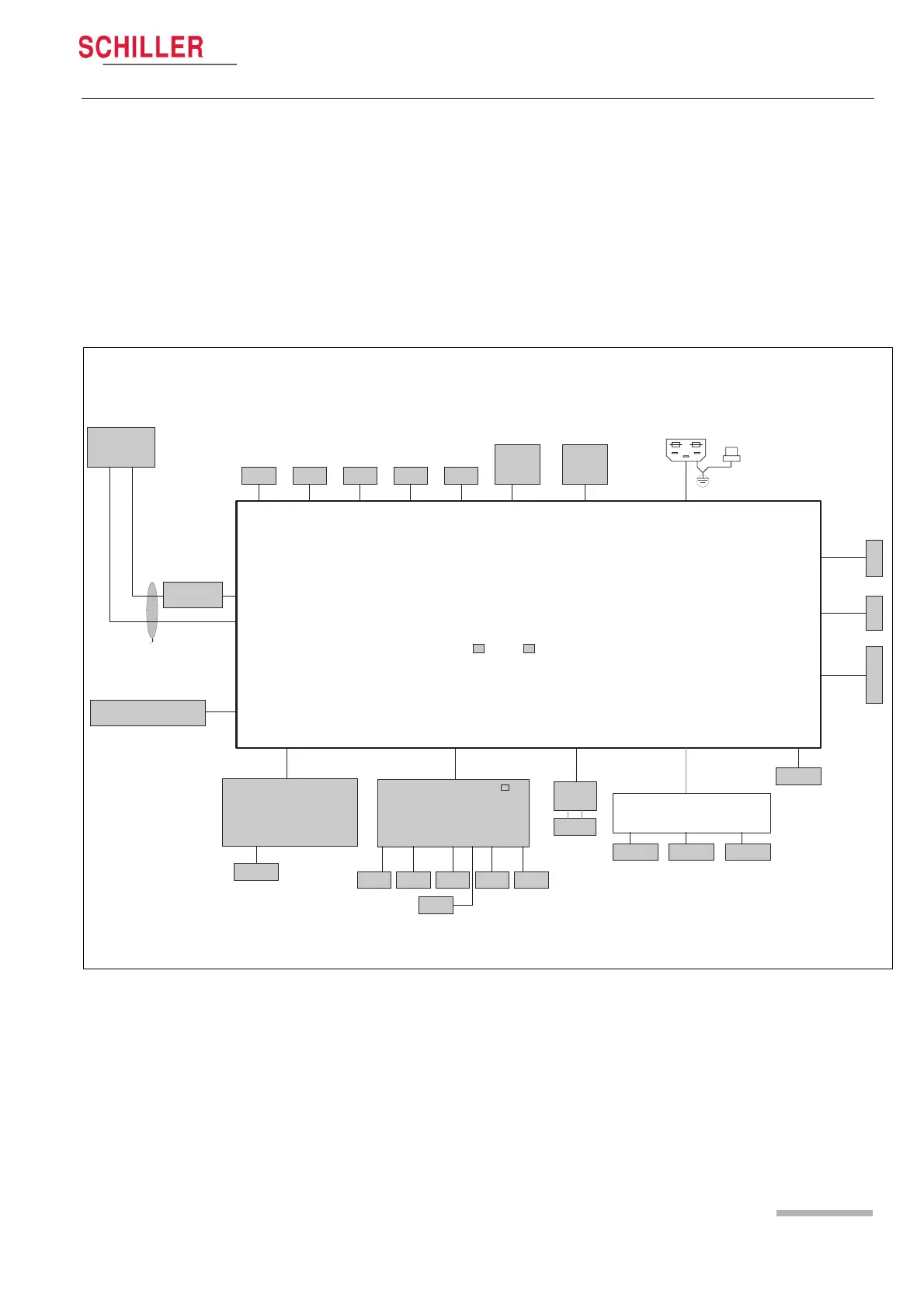
10.2 Circuit and functional illustrations
The circuit diagrams are confidential. Therefore only the high level drawings are
provided here.
10.2.1 Connection block diagram
MAINS INPUT
POTENTIAL-
AUSGLEICH
MK22-1
MAINBOARD
INT.BATT.
VGA
NIBPSpO2
SPIROERGO RESIST
USB B
Ext. NIBP
ModemUSB A SDCARD
TRADMILL
LAN
DC OUT
Anal. ERGO/QRS
PMD
TPH-MOTOR
PD-MOTOR
TPH
LCD
LCD SIGNAL
LCD BACKLIGHT
MK22-2
EKG-INTERFACE
PAT
TP 4, 5, 6
P10P23
P9
P27
P5
P3
P18
P21 / P22
P40
P13
P11A
P7
P26 P28 P29 P14 / P24 P15 / P25
P17
P6
P23
P12
21.6V DC
P2 BDM
KEYBOARD
Backlight
DC IN
P19
2 x 200mAT (230VAC / 50HZ)
P11
P11
MK17-5
Printer Interface
MK17-4
MK22-7
Kommunikationsmudul
P1 Test
MK22-8MK22-9
RS-232 RS-232
MDR-14
RS-232
RS-232
(SP10plus)
2 x 315mAT (115VAC / 60HZ)
P36 BDM
P10
P30 P31 P32 P33 P34 P35