Page 37
Functional Checks 5
AT-10 plus Service Handbook Functional checks and tests 5.3
Art.-no.: 2.540043 Rev.: a
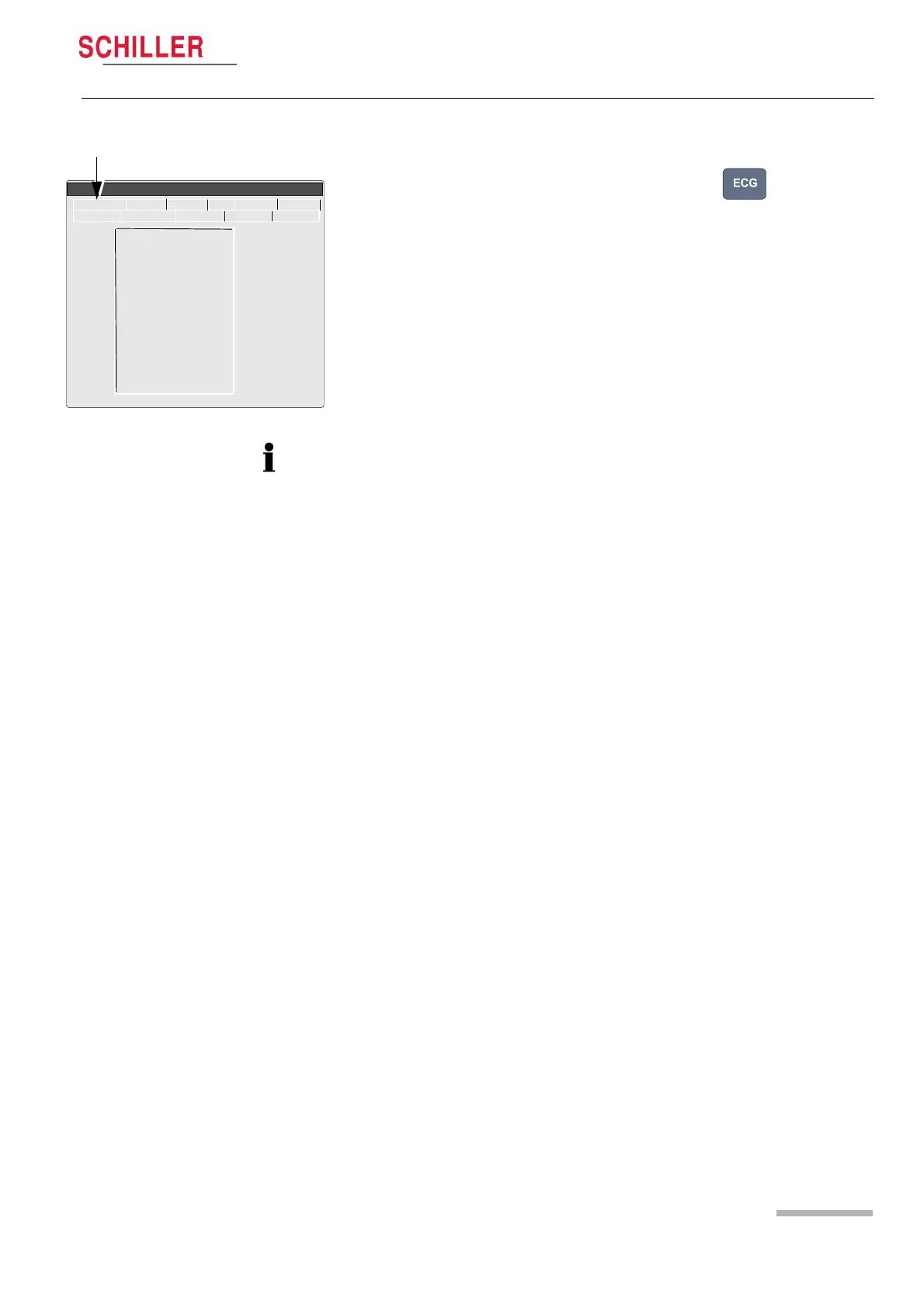
5.3.8 ECG amplifier and patient cable test
1. With a patient simulator connected, press the ECG key . The electrode
screen is displayed (this screen is also displayed in the service screen (see page
20).
2. Disconnect ECG patient simulator. Check the following:
– device beeps 4 times
– all lead designations highlighted
– the mV reading for all leads is -350 to -550 mV
3. Connect ECG simulator and setup HR to 60 b/min, no arrhytmias.
4. Check the following:
– all leads stops blinking
– the mV reading for all leads is -15 ...+15 mV
5.3.9 External printer test
Only with the Comms Module. At the time of print this was not available
5.3.10 Communication (RS-232) test
Only with the Comms Module. At the time of print this was not available.
Lead Test (mV)
RA 5
LA 5
C1 5
C2 5
C3 5
C4 5
C5 5
C6 5
C7 497
C8 495
C9 498
C10 498
LOFF 0F00
ECG NIBP Spiro HW- I/O +
Service
Character Colour Printer Key Battery
Softwar
• When a standard 10-lead cable is connected, check RA, LA, and C1 to C6 only.
• Additionally check C7, C8, and C9 when a 13 lead patient cable is used.
• Additionally check C7, C8, C9 and C10, when a 14 lead patient cable is used.
• LOFF is a register for factory use only (for lead confirmation).