4 Service Screen
4.1 ECG
AT-10 plus
Page 20
Art.-no.: 2.540043 Rev.: a
4 Service Screen
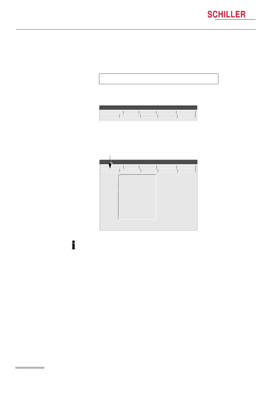
To enter the service screen press the following key sequence:
A number of tabs at the top of the screen give the following options:
4.1 ECG
To check the electrode resistance and the integrity of the cable, click the ECG icon.
This gives electrode dc offset and is the voltage drop in the patient cable and
electrodes. The result column gives the detected voltage for each electrode in
millivolts measured between the electrode on the left leg and each of the individual
electrodes.It can indicate any faults in the patient cable or patient electrode. The
measured voltage value will depend on where the electrodes are connected. The
voltage readings that can be expected are as follows:
With patient connected: ± 100mV: Good connection, low resistance. An offset of up to ±300mV will give an
acceptable recording.
With patient simulator connected: ± 20 mV: This will depend on the patient simulator used and must be taken as a
flexible measurement.
With all electrodes shorted together: ± 20 mV.
No patient cable connected: -350 to -550mV.
‘.’ > ‘.’ > ‘S’ (full stop key pressed twice, followed by ‘s’).
ECG NIBP Spiro HW-Config. I/O + ports
Service
Character Colour Test Battery
Software
Lead Test (mV)
RA 5
LA 5
C1 5
C2 5
C3 5
C4 5
C5 5
C6 5
C7 5
C8 5
C9 5
ECG NIBP Spiro HW-Config. I/O + ports
Service
Character Colour Test Battery
Software
The electrode resistance check is provided as an integrity check for the electrode
resistance and patient cable if suspected of being faulty.
 Loading...