11 Special Test Equipment
11.1 RS test plug
AT-10 plus
Page 72
Art.-no.: 2.540043 Rev.: a
11 Special Test Equipment
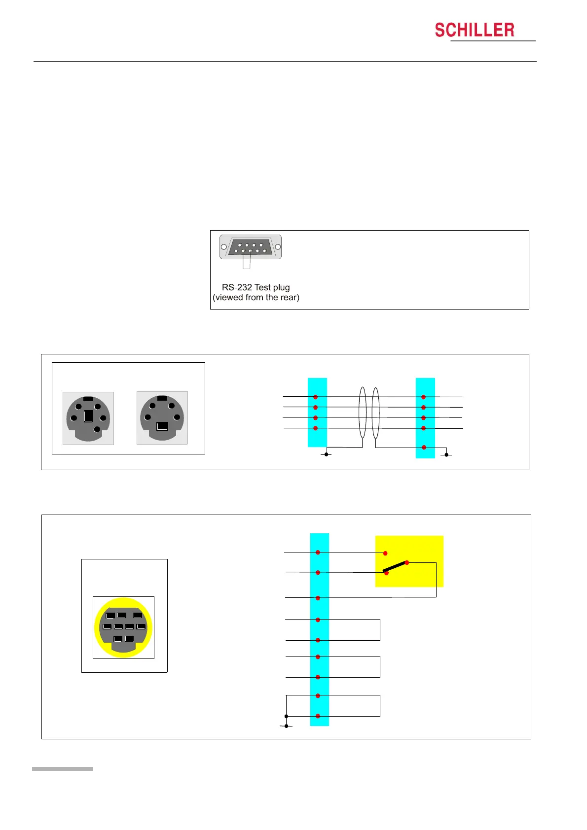
The following test plugs and equipment must be fabricated to carry out the interface
tests (see page 24).
11.1 RS test plug
11.2 DC In/Out cable assembly
11.3 ERGO connector and switch
Using an RS plug, solder together pins 2 and 3.
P18 - DC out P17 - DC in
DC Out 1
DC Out 1 Gnd
DC Out 2
DC Out 2 Gnd
DC In 1 +
DC In 1 -
DC In 2 +
DC In 2 -
1
2
3
4
2
3
4
5
1
Shield
P18 (DC OUT)
front view
1
3
4
2
P17 (DC IN)
front view
2
4
5
3
1
P19 - ERGO
TMUP
TMDOWN
FOOTIN
9
8
7
Switch
QRSOUT
RPMin
6
1
LOADOUT
LOADIN
3
2
5
4
Shield
P19 (ERGO)
front view
2
1
4536
789