Installation Notes
L Read the precautions and instructions before installing and
using this lock. Save documentation for future reference
L Default codes and model number are located on a label on
the back of the inside assembly. Note or photograph these
codes and save them in a safe place.
Installation Preparation
A Check door preparation.
2³⁄₄" (70 mm)
OR
2³⁄₈" (60 mm)
1³⁄₈" (35 mm) TO
2" (50 mm)
1¹⁄₂" (38 mm)
OR
2¹⁄₈" (53 mm)
Hole
1" (25 mm)
Door Edge
Backset
B Install strike plate and dust box (if included).
Strike plate
Use the strike plate as a
template to drill the latch
and screw holes and chisel
out the mortise. The strike
plate must t ush with the
surface of the door jamb.
The hole must be at least
1" (25mm) deep.
C Adjust bolt, if necessary.
Ca If your backset is 2C\,”, skip this step. If your backset is
2C\v", adjust your bolt length. Twist the bolt as shown.
180º
2
8
3
2
8
3
2
4
3
Cb If your door edge does not have a mortise cut out, adjust
your bolt as shown.
D Install bolt.
Bolt must remain retracted throughout installation!
Wood block
(not included)
OR
Lock Installation
1 Install keypad assembly.
1a If the hole through your door
is 2Z\,”, skip this step. For 1Z\x”
hole: 1 Remove black rubber
backplate from the outside
assembly. 2 Pry the adapter
collar o with a screwdriver.
Reinstall backplate and
continue.
1b Install keypad assembly. Route driver bar through the
slot on the bolt. Route cable under the bolt.
Cylinder assembly may fall out of keypad assembly. Hold
cylinder assembly in while installing mounting plate on
the next step.
2 Install mounting plate. Secure with screws.
Route cable through notch in mounting plate, then tuck
behind tab.
Mounting plate screws are secured into holes on the
cylinder assembly. Hold cylinder assembly in while
securing screws.
Route cable
through hole
Mounting screw, x2 black
Tuck
behind tab
3 Install inside assembly.
3a Remove battery cover from inside assembly.
L Default codes are on
label on mounting
plate. Make a note of
the codes.
3c Connect and route cable from keypad assembly.
Connect
3d Use 2 screws to secure inside assembly. Do not pinch
cable.
x2 silver
4 Install batteries and cover.
Use 4 (four) new, high-quality alkaline batteries.
5 Enter default code.
Default codes are on label on the back of inside assembly
and on the front of the English language user guide. Enter a
default user code, then press the lock button to start
set up procedure. Set up is complete when bolt stops moving.
Continue to user guide.
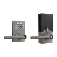
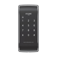
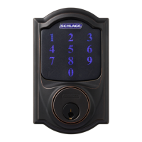
JBE109
Connected
Deadbolt
Tools Needed
• Phillips screwdriver
Optional
• Flathead screwdriver
• Chisel
• Hammer
• Piece of wood
• Drill
Contact Customer Support
888-805-9837
© Allegion 2020
JBE109 Connected Deadbolt IS Rev. 06/20-d
1
2