Installation Notes
L Read the precautions and instructions before installing and
using this lock. Save documentation for future reference.
L Default codes and model number are located on a label on
the back of the inside assembly. Note or photograph these
codes and save them in a safe place.
Installation Preparation
A Check door preparation.
2³⁄₄" (70 mm)
OR
2³⁄₈" (60 mm)
2¹⁄₈" (53 mm)
Hole
1" (25 mm)
Door Edge
BACKSET
1³⁄₈" (35 mm) TO
2" (50 mm)
B Install strike plate and dust box (if included).
Strike Plate
Dust box
Use the strike plate as a
template to drill the latch
and screw holes and chisel
out the mortise. The strike
plate must t ush with the
surface of the door jamb.
The hole must be at least
1” (25mm) deep.
C Adjust latch, if necessary.
Ca Pull the latch as shown to adjust length for 2C\,” or 2C\v”
backset.
2-3/8”(60mm)
CORRECT
INCORRECT
2-3/4”(70mm)
OR
Cb If your door edge does not have a square or rounded
corner cut out around the hole for the latch, adjust your
latch as shown.
D Set lever rotation direction.
Da Remove screw from back of inside assembly. Rotate
lever to desired position, then reinstall #1 Phillips screw
to hole shown below.
Inside assembly
Outside assembly
Db Remove screw from back of keypad assembly. Rotate
lever to desired position, then reinstall screw to hole
shown below.
Inside assembly
Outside assembly
Dc If your lever style is symmetrical (does not have a ared
or curved end), skip this step. It may be necessary to
switch levers after lever is rotated to desired position.
The tip of the levers should point down.
Insert pin wrench into small
hole near base of lever, then
pull lever to remove. Remove
both levers, then reinstall levers
to the opposite side they were
removed.
Lock Installation
1 Install latch.
OR
Wood block
(not included)
2 Install keypad assembly.
Route cable over the latch.
3 Install mounting plate. Secure with screws.
Route cable through notch in mounting plate, then tuck
behind tab.
Tuck
behind tab
Route wire
through hole
x2
4 Install inside assembly.
L Default codes are on label on back of the inside assembly.
Make a note of the codes.
4a Connect cable from keypad assembly.
4b Use 2 screws to secure inside assembly.
x2
5 Install batteries and cover.
Use 4 (four) new, high-quality alkaline batteries.
6 Enter default code.
Default codes are on label on lock. Enter a default user code
to complete installation. Continue to user guide.
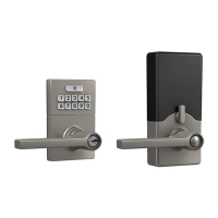
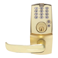
JFE109 Connected Lever
Tools Needed
• Phillips screwdriver
Optional
• Pin wrench (for non-
symmetrical levers)
• Flathead screwdriver
• Chisel
• Hammer
• Piece of wood
• Drill
Contact Customer Support
888-805-9837
© Allegion 2020
JFE109 Connected Lever IS Rev. 08/20-e
G59-KPLAF14A_00