EasyManua.ls Logo

Schlage M400 Series User Manual

Schlage M400 Series
12 pages
To Next Page IconTo Next Page
Page #1 background imageLoading...
Page #1 background image
M400 Series
Electromagnetic Locks
Installation Instructions for Double Locks
M422, M452, M492
FEATURES
Automatic Voltage Selection (AVS)
Magnet immediately detects 12VDC or 24VDC when power
is connected.
Anti-Tamper Switch (ATS)
An indication is provided should the magnet cover become
unsecured from lock.
Magnetic Bond Sensor (MBS)
Detects proper bond between magnet and armature. It can
be monitored remotely and locally with an LED.
LED
Provides local indication of MBS status.
Door Position Switch (DPS)
Indicates whether door is open or closed. this feature is used
in conjunction with the MBS.
Relock Time Delay (RTD)
Relock time can be changed. Range is 1 - 30 seconds.
MODELS
M422 (Traffi c Control)
UL1034 and 10C/500lb and 3hr rating
M452 (High Security)
UL1034 and 10C/1000lb and 3hr rating
M492 (Max Security)
UL1034 and 10C/1500lb and 3hr rating
TRIMS
Basic
Auto Voltage Selection (AVS) for 12 or 24VDC
Plus
Basic features + Door Position Switch (DPS), Magnetic Bond
Sensor (MBS), Relocking Time Delay (RTD), LED Status
Indicator (LED) and Anti-Tamper Switch (ATS)
UL Requirements:
Units shall not impair operation of panic hardware mounted on door.
Units shall not impair intended operation of an emergency exit.
Units/Models are intended to be connected to UL Listed Equipment, not
intended for Burglar or Fire Alarm Initiating or Indicating Devices.
Ambient Conditions - “For Indoor Use Only”
This device complies with part 15 of FCC rules.
Operation is subject to following two conditions:
1. This device may not cause harmful interference.
2. This device must accept any interference received, including any
interference that may cause undesired operation. Changes or modifi cations
not expressly approved by party responsible for compliance could void
user’s authority to operate equipment.
Question and Answer IconNeed help?

Do you have a question about the Schlage M400 Series and is the answer not in the manual?

Schlage M400 Series Specifications

General IconGeneral
SeriesM400
TypeMortise Lock
ANSI GradeGrade 1
Backset2-3/4 inches
Door Thickness1-3/4 inches to 2-1/4 inches
Deadbolt Throw1 inch

Summary

Product Features and Models

Automatic Voltage Selection (AVS)

Magnet detects 12VDC or 24VDC automatically when power is connected.

Anti-Tamper Switch (ATS)

Indicates if the magnet cover becomes unsecured from the lock.

Magnetic Bond Sensor (MBS)

Detects proper bond between magnet and armature, monitorable locally and remotely.

Door Position Switch (DPS)

Indicates door status (open/closed), used with MBS.

Relock Time Delay (RTD)

Adjustable relock time range from 1 to 30 seconds.

M422 (Traffic Control) Model

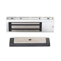
Model rated for UL1034, 500lb holding force, and 3hr fire rating.

M452 (High Security) Model

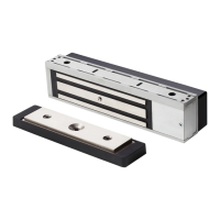
Model rated for UL1034, 1000lb holding force, and 3hr fire rating.

M492 (Max Security) Model

Model rated for UL1034, 1500lb holding force, and 3hr fire rating.

Basic Trim

Features Auto Voltage Selection (AVS) for 12 or 24VDC.

Plus Trim

Includes DPS, MBS, RTD, LED, and ATS features.

Electrical Specifications

Lock Installation Steps

Lock Orientation

Ensuring wiring covers are in the middle and magnet orientation for double locks.

Reorient Magnet in One Lock

Procedure for removing covers, blocks, and rotating magnet for correct orientation.

Place Template and Mark Holes

Positioning template on door centerline and marking holes for installation.

Install MBS Indicator (Plus Models Only)

Remove Cover

Step to remove the lock cover to access internal components.

Drill Hole for MBS Indicator

Instructions for drilling specific holes for the MBS indicator installation.

Install MBS Indicator

Procedure for installing the MBS indicator into the lock assembly.

Install ATS (Plus Models Only)

Remove End Block and Wiring Cover

Step to remove end block and wiring cover for ATS installation.

Install ATS and Reassemble

Procedure for installing the ATS and reassembling the lock.

Attach Armatures to Doors

Install Armatures as Shown

Instructions for attaching armatures to the doors according to the diagram.

Install Mounting Brackets into Frame

Attach Mounting Brackets Temporarily

Temporarily attach mounting brackets using alignment tool and screws.

Remove Wiring Covers and End Blocks

Remove covers and end blocks from the lock for installation.

Slide One Magnet onto Bracket

Instruction for sliding the first magnet onto the mounting bracket.

Slide Second Magnet onto Bracket

Instruction for sliding the second magnet onto the mounting bracket.

Align Magnets to Armatures

Aligning magnets with armatures by closing doors and pressing magnets.

Remove Magnet and Snug Outer Screws

Remove magnet and snug two outer screws for initial mounting.

Align Center of Brackets Using Alignment Tool

Aligning bracket centers using the alignment tool and tightening screws.

Verify Magnet Adjustment

Check for full magnet contact with armatures and repeat steps if needed.

Prepare Additional Holes

Drilling additional holes for mounting, using #10-24 tap if metal is reinforced.

Install Eight (8) Screws

Install and fully tighten eight screws after alignment and hole preparation.

Attach Magnets to Mounting Brackets

Slide First Magnet onto Bracket

Procedure for sliding one magnet onto the mounting bracket.

Install Joining Block into Lock

Installing the joining block into the lock assembly.

Slide Second Magnet onto Bracket

Procedure for sliding the second magnet onto the mounting bracket.

Secure Locks with Four (4) Screws

Securing the lock assembly using four screws.

Connect Wiring to Board (Standard Model)

Review Wiring Connections

Diagram and explanation of wiring connections for standard models.

Connect Wires to Boards

Connecting the magnet and door frame wires to the mag lock boards.

Install Covers

Final step of installing the covers after wiring connections are made.

Connect Wiring to Board (Plus Model)

Connect Outside Wires to Boards

Connecting wires for Normally Open (NO) or Normally Closed (NC) configurations.

Review Plug Locations

Identifying plug locations on the Mag Lock Board for various components.

Connect Plugs to Boards

Connecting wires from LED, MBS, and Magnet to the respective board terminals.

Connect ATS Wires

Wiring the Anti-Tamper Switch (ATS) to the lock board terminals.

Install Covers

Finalizing the installation by installing the covers over the wiring.

Related product manuals